

A device for microwave fluidized drying lignite
A fluidized drying and microwave technology, applied in the drying of solid materials, heating to dry solid materials, drying, etc., can solve the problems of reducing the quality of coal coking, complex equipment and technology, and failing to achieve the effect of quality improvement. And the microwave field is evenly distributed, the effect of solving the insufficient penetration depth and increasing the gas-solid contact area
- Summary
- Abstract
- Description
- Claims
- Application Information
AI Technical Summary
Problems solved by technology
Method used
Image

Examples
Embodiment Construction
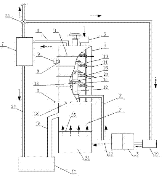
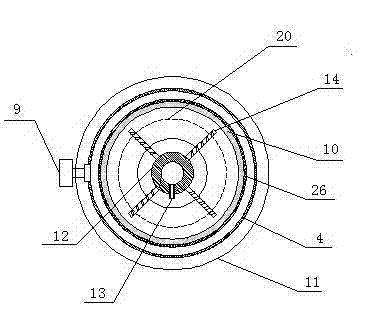
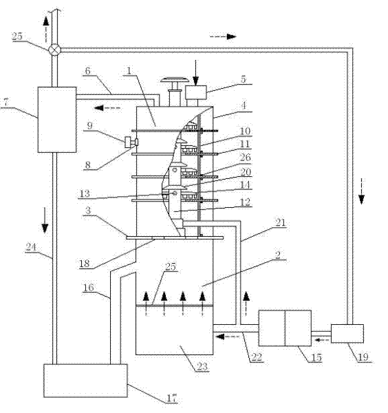
[0018] See figure 1 , figure 2 , a device for microwave fluidized drying lignite, including a microwave heating chamber 1, the bottom of the microwave heating chamber 1 is connected to the fluidized bed 2 through a flange 3, and the flange 3 is provided with a connection between the microwave heating chamber 1 and the fluidized bed 2 Material hole 18; Microwave heating chamber 1 comprises the cylindrical metal furnace shell 4 that can shield microwave, is provided with material inlet 5 and flue gas port 6 on the top of furnace shell 4, and furnace shell 4 is provided with 4 microwave generating devices along the circumference to dissipate microwaves. It can be fed into the microwave heating chamber 1. The microwave generating device is composed of a microwave feed port 8 arranged on the furnace shell 4 and a microwave source 9 installed on the microwave feed port 8. There is also a microwave penetrating microwave oven inside the furnace shell 4. The cylindrical ceramic furna...
PUM
 Abstract
Description
Claims
Application Information