Ventilation and heat dissipation system of transformer room in semi-buried box-type substation

A box-type substation and transformer room technology, which is applied in the cooling/ventilation of substation/switchgear, power distribution substation, substation/power distribution device shell, etc., which can solve the problem of affecting the safety of pedestrians and vehicles, the inability to form convection, and the intrusion of rainwater, etc. problem, to ensure the ventilation effect and reduce the effect of water ingress

Inactive Publication Date: 2011-11-30
浙江安可电气科技有限公司
View PDF7 Cites 7 Cited by
  • Summary
  • Abstract
  • Description
  • Claims
  • Application Information

AI Technical Summary

Problems solved by technology

The disadvantages of this method are: 1. The opening at the bottom of the louvered vent is often close to the ground, and rainwater can easily flow back into the transformer room, especially in southern regions and eastern coastal cities, where the precipitation is large, and the probability of water ingress is low. It will be lifted, which will affect the safe and normal operation of the transformer; 2. There are no air inlets and outlets with different heights, so convection cannot be formed, and the natural ventilation effect is poor
This design of the upper box and the lower box share the ventilation channel, and there are also shortcomings: 1. The upper and lower boxes share the ventilation channel, and t

Method used


Image

  • Ventilation and heat dissipation system of transformer room in semi-buried box-type substation
  • Ventilation and heat dissipation system of transformer room in semi-buried box-type substation
  • Ventilation and heat dissipation system of transformer room in semi-buried box-type substation

Examples


Embodiment Construction

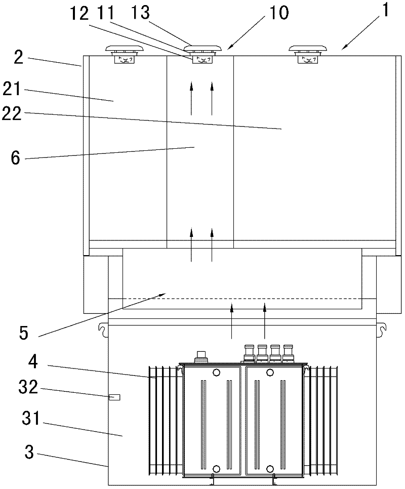
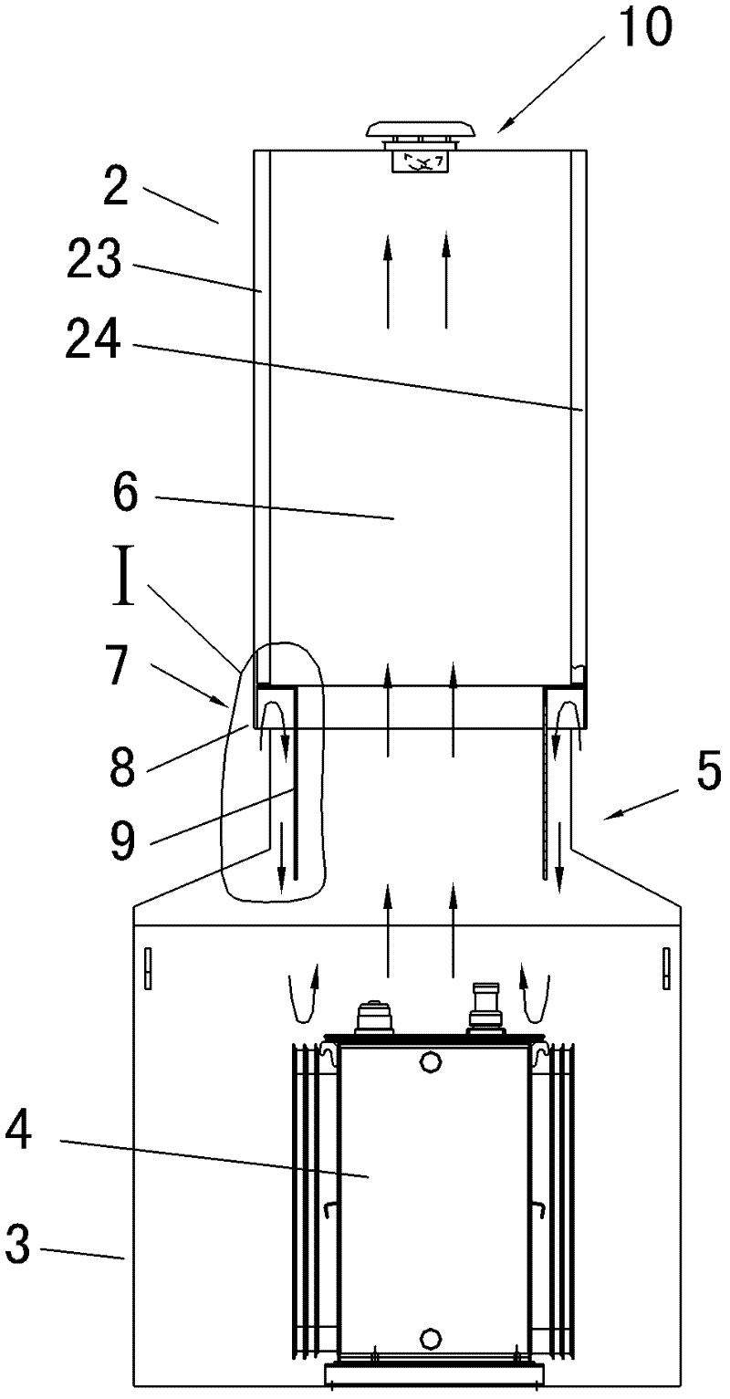
[0027] The semi-buried box-type substation 1 that the present invention relates to, such as figure 1 shown. The upper part is an upper box body 2, and its internal space constitutes a switch cabinet room (21, 22), which has a switch cabinet (not shown in the figure); the lower part is a lower box body 3, and its internal transformer room 31 is equipped with a transformer 4. The top of the lower box is the neck 5, and most of the neck 5 is exposed to the ground when installed on site, and the top is connected with the upper box 2.

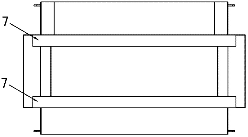
[0028] The ventilation system of this embodiment, such as Figure 1 to Figure 4 shown. The lower air outlet 7 of the transformer chamber 31 is arranged on the front and rear sides above the lower box neck 5 . A ventilating compartment 6 penetrating up and down is arranged in the upper case 2 , the lower part of the ventilating compartment 6 leads into the transformer chamber 31 , and the upper part opens at the top of the upper case to form an up...


PUM


Abstract

The invention provides a ventilation and heat dissipation system for a transformer room of a semi-buried box-type substation, comprising an upper box as a switch cabinet room and a lower box as a transformer room, the neck of the lower box is exposed to the ground. It sets the lower air outlet of the transformer room on one side or both sides above the neck of the lower box; in the upper box, a ventilation compartment that penetrates up and down is set, the lower part is connected to the transformer room, and the upper part is formed by opening on the top of the upper box. The upper air outlet is equipped with an exhaust fan; the upper box and the lower box are not connected except for the ventilation compartment. The ventilation compartment also serves as access for maintenance personnel into the transformer room. The lower tuyere of the present invention is higher than the ground plane, and rainwater is difficult to enter the transformer room. The lower air outlet and the upper air outlet have a large height difference, which is easy to form convection of cold and hot air. The ventilation system of the transformer room and the switch cabinet room are separated, which improves the ventilation efficiency.

Description

technical field [0001] The invention relates to the technical field of semi-buried box-type substations, in particular to a ventilation and cooling system for semi-buried box-type substations. Background technique [0002] The semi-buried box-type substation is usually composed of a lower box with a built-in transformer buried in the underground part and an upper box with a built-in switch cabinet in the ground part. The inner space of the lower box is called the transformer room, and the inner space of the upper box is called the switch cabinet room. The transformer will generate heat during operation, and a ventilation and heat dissipation system is required for ventilation and cooling. The ventilation and heat dissipation system of the existing semi-buried box-type substation transformer room is generally provided with a ventilation channel under the bottom of the upper box (that is, the junction of the upper and lower boxes). The junction is slightly higher than the gro...

Claims


Application Information

Patent Timeline
IPC IPC(8): H02B1/56H02B1/28H02B7/06
Inventor 陶勤杨永林潘吉潘健叶阿明孙榆
Owner 浙江安可电气科技有限公司
Why Eureka
Try Eureka