
High-power wind power converter energy storage capacitor charging circuit

A technology of wind power converter and energy storage capacitor, applied in wind power generation, electrical energy storage systems, and conversion equipment without intermediate conversion to AC, can solve the problem of inaccurate measurement of current sensors, high cost of charging loops, and reduced equipment efficiency. and other problems, to achieve the effect of fast charging speed, good harmonic suppression effect and low cost

Inactive Publication Date: 2011-11-30
JIANGSU KAIFAN ELECTRICAL APPLIANCES
View PDF3 Cites 4 Cited by
  • Summary
  • Abstract
  • Description
  • Claims
  • Application Information

AI Technical Summary

Problems solved by technology

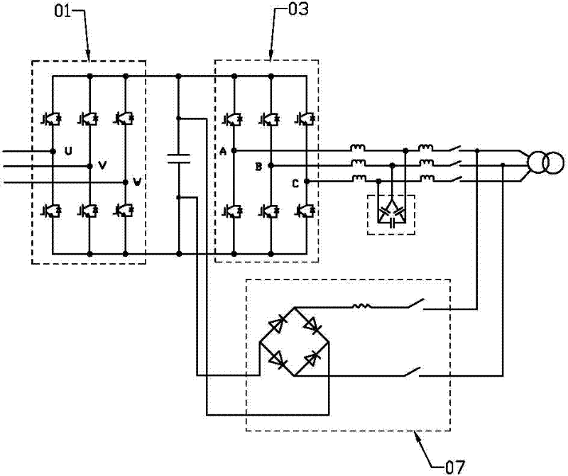
This circuit and method is currently the mainstream charging method for MW-level converters. Its defects are: 1. The charging time is long; 2. The harmonic current component in the charging current is very large. Although it will not affect the performance of the energy storage capacitor, it will produce The additional harmonic loss reduces the efficiency of the equipment, and may cause inaccurate measurement of the voltage and current sensors at both ends of the energy storage capacitor; 3. Due to the setting of a separate rectifier module, the cost of its charging circuit is relatively high

Method used


Image

  • High-power wind power converter energy storage capacitor charging circuit
  • High-power wind power converter energy storage capacitor charging circuit
  • High-power wind power converter energy storage capacitor charging circuit

Examples


Embodiment Construction

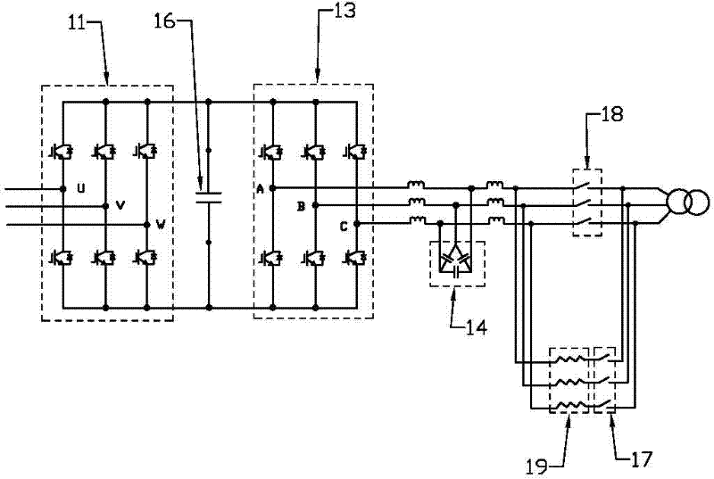
[0010] Such as image 3 As shown, the wind power converter energy storage capacitor charging circuit of the present invention has the same machine-side rectifier circuit 11, grid-side inverter circuit 13, and machine-side switch ( Not shown), LCL filter circuit 14, grid-side switch 18, energy storage capacitor 16, in addition, a charging resistor 19 is connected in parallel at the grid-side switch, and the charging resistor is turned on and off by a charging switch 17 connected in series with it.

[0011] In the working process of the present invention, before the converter is not working, that is, when both the machine-side switch and the grid-side switch are turned off, the charging resistor is connected, and the original continuous current on the bridge arm of the IGBT switch tube in the IGBT power unit is used to pass through the grid voltage. The current diode precharges the energy storage capacitor, so that the DC bus voltage reaches a capacitor safe voltage range before...


PUM


Abstract

The invention belongs to wind power generation equipment, and relates to a charging circuit for an energy storage capacitor of a high-power wind power converter. The circuit includes a machine-side rectifier circuit and a grid-side inverter circuit connected between the generator and the power grid; the machine-side rectifier circuit is composed of an IGBT power unit, and is connected to the generator through a machine-side switch; the grid-side inverter circuit consists of It is composed of IGBT power unit, and connected to the power grid through LCL filter circuit and grid-side switch in sequence; its feature is that the charging resistor is connected in parallel at the grid-side switch, and the charging resistor is controlled by the charging switch connected in series. The invention can ensure that the DC bus voltage reaches a capacitor safety voltage range in advance before the converter starts to work, and prolongs the service life of the capacitor; it not only has a simple circuit structure and low cost, but also has fast charging speed, high charging voltage and harmonic suppression effect it is good.

Description

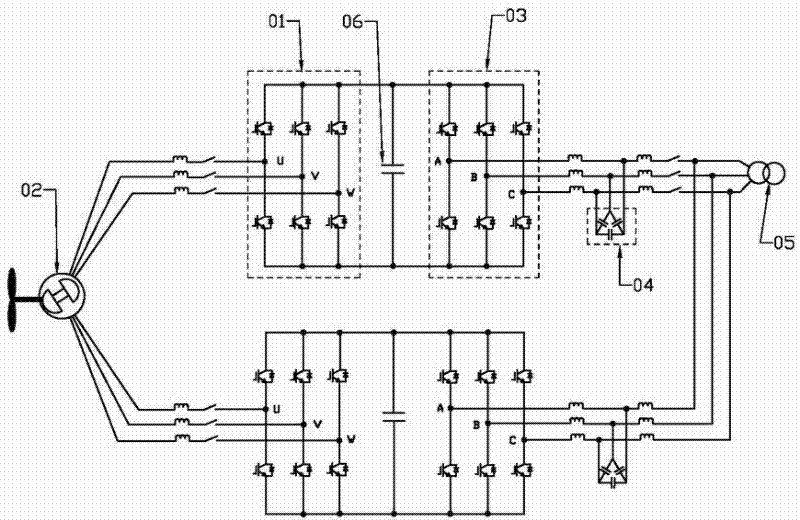
technical field [0001] The invention belongs to wind power generation equipment, and relates to a charging circuit for an energy storage capacitor of a high-power wind power converter. Background technique [0002] In the main circuit of the voltage-type PWM high-power rectifier (VSR) of the wind power generation system, as attached figure 1 As shown, the DC side includes a machine-side rectifier circuit 01 composed of IGBT power units, and the machine-side rectifier circuit is connected to the generator 02 through a machine-side switch. The inverter circuit is connected to the grid 05 through the LCL filter circuit 04 and the grid side switch. On the DC side, the energy storage capacitor 06 is usually used for DC energy storage. The energy storage capacitor can not only buffer the energy conversion between the AC side and the DC side load, stabilize the VSR DC side voltage, but also suppress the DC side harmonic voltage. However, in high-power MW-level wind power converte...

Claims


Application Information

Patent Timeline
Patent Type & Authority Applications(China)
IPC IPC(8): H02M3/07H02J15/00H02J3/38
CPCY02E10/763Y02E70/30Y02E10/76
Inventor 丁印福张波涛朱琴华张海莲武美娜
Owner JIANGSU KAIFAN ELECTRICAL APPLIANCES
Learn More