heating appliances

A technology for heating appliances and heating parts, which is applied in the direction of heating appliances for therapeutic treatment, cooling appliances for therapeutic treatment, contraceptives, etc., and can solve the problems of inability to provide heating effects, insufficient heat production by chemical heaters, and exothermic compositions. Difficulty in contact with air and other issues to achieve a stable heating effect

Active Publication Date: 2011-11-30
KOBAYASHI PHARMA CO LTD
View PDF10 Cites 3 Cited by
  • Summary
  • Abstract
  • Description
  • Claims
  • Application Information

AI Technical Summary

Problems solved by technology

[0006] However, when the cold protector (scarf) of Patent Document 3 is used around the neck, the outside of the chemical heater (i.e., the face that does not touch the body) is covered with cloth; therefore, the exothermic composition inside the chemical heater cannot full exposure to air
Also, scarves are often wrapped in multiple layers when in use, making contact of the exothermic composition with air more difficult
Therefore, the scarf cannot provide the desired heating effect due to insufficient heat generation by the chemical heater inside the scarf

Method used


Image

  • heating appliances
  • heating appliances
  • heating appliances

Examples


preparation example Construction

[0111] (4) Preparation of heat generating part

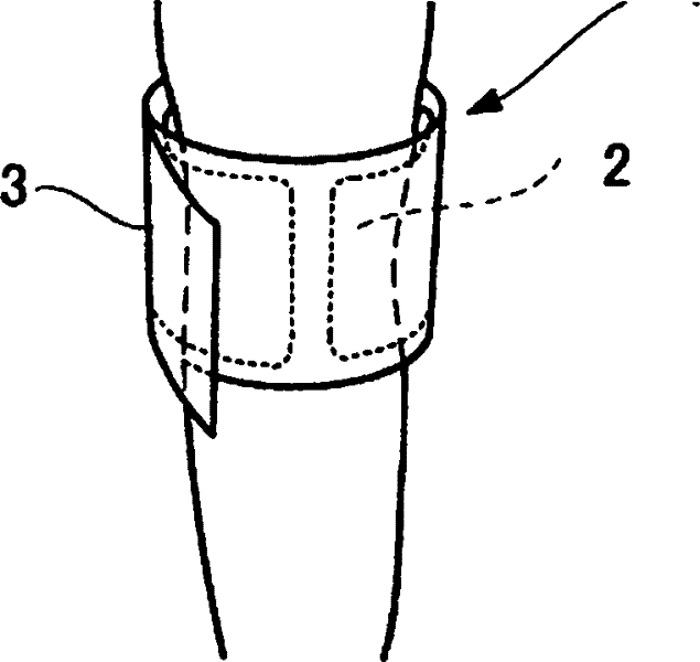
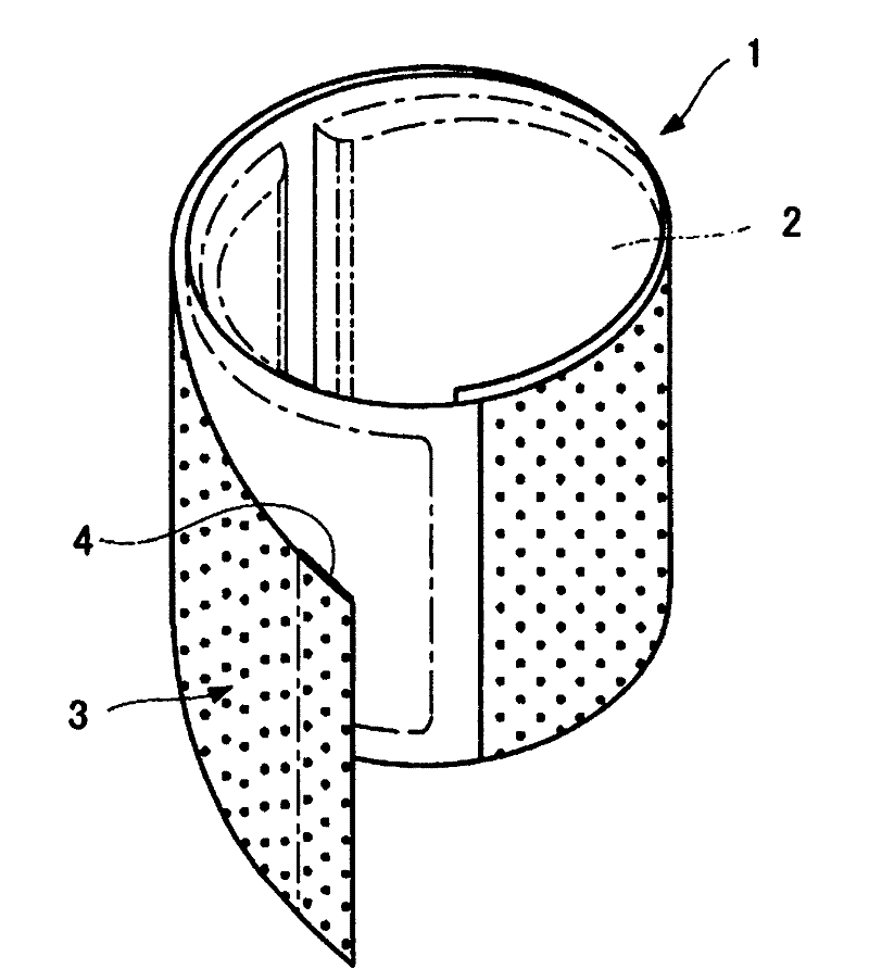
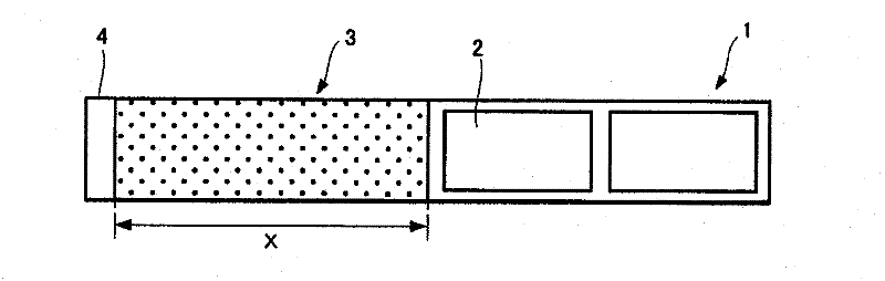
[0112] The heat generating portion described above is obtained by bonding the first and second sheets in such a manner that the heat releasing composition is enclosed in one or more parts. When the first and second sheets respectively use laminates, the first and second sheets are bonded to each other such that the non-woven fabric forming each laminate faces outward (that is, the side that is in contact with the closed exothermic composition) on the contrary). At this time, all parts of the heat generating portion except the respective parts were bonded so that the respective parts enclosed with the exothermic composition were formed. For example, in image 3 , the first and second sheets are bonded to each other in the region of the heat generating portion 1 other than the member 2 .

[0113] Examples of usable bonding methods include, but are not limited to, the aforementioned methods of thermal bonding and bonding of resi...

Embodiment

[0132] The present invention will be described in more detail below with reference to the following Examples and Comparative Examples; however, the present invention is not limited to these Examples.

[0133] Examples and Comparative Examples

[0134] Manufacturing has image 3 A heating appliance of the structure shown.

[0135]

[0136] 1) Exothermic composition

[0137] The exothermic composition was prepared by mixing iron powder with a particle size of 50 μm, activated carbon with a particle size of 200 μm, salt with a particle size of 380 μm, water, vermiculite with a particle size of 100 μm, and acrylic acid polymer with a particle size of 380 μm. The amounts of iron powder, activated carbon, sodium chloride, water, vermiculite and sodium polyacrylate in the exothermic composition were 55%, 13%, 1%, 26%, 3% and 2% by mass, respectively.

[0138] The exothermic composition was prepared according to the method described above.

[0139] 2) First sheet

[0140] First...


PUM

PropertyMeasurementUnit
particle sizeaaaaaaaaaa

Abstract

An object of the invention is to provide a heating device that is securely held in its worn position, and that can exhibit a sufficient heating effect. A heating device comprising: a heat-generating portion having an exothermic composition enclosed in one or more sections, the exothermic composition generating heat by contact with air; and an elastic band portion; (1) the band portion surrounding all or a portion of the heat-generating portion to keep the heat-generating portion in contact with the body; (2) the band portion being connected to an end of the heat-generating portion; (3) a face of the heat-generating portion that is brought into contact with the band portion having a moisture permeability of 340 to 610 g / m2 per day, as measured according to Method A (Humidity Sensor Method) defined in JIS K7129; and (4) the band portion having an air permeability of 3 s / 300 cc to 61 s / 300 cc, as measured according to JIS P 8117-1998: Paper and board—Determination of air permeance and air resistance: Gurley method.

Description

technical field [0001] The present invention relates to heating appliances and in particular to therapeutic or rehabilitation appliances for wrists, ankles, knees, elbows or necks. Background technique [0002] Heating appliances with heat generating parts have previously been proposed as therapeutic or rehabilitation appliances. Such a heating device generates heat when the exothermic composition inside the heat-generating part comes into contact with air, thereby exerting a heating effect on the affected part. [0003] For example, Patent Documents 1 and 2 disclose heating appliances made in the form of a cylinder holding a chemical heater. These braces are worn on an afflicted part, such as a wrist or an ankle, and exert a heating effect on the afflicted part by the heat generated by a chemical heater. [0004] However, when the braces of Patent Documents 1 and 2 are worn for a long time, they are displaced from their original positions due to movement of the wearer or ...

Claims


Application Information

Patent Timeline
Patent Type & Authority Applications(China)
IPC IPC(8): A61F7/08
CPCA61F2007/0228A61F7/034A61F7/02A61F2007/0258Y10T29/49982
Inventor 松尾笃士
Owner KOBAYASHI PHARMA CO LTD
Why Eureka
Try Eureka