System and method capable of controlling viscosity of electric spindle lubricating fluid

A technology of electric spindle and lubricating fluid, which is applied in the direction of control/adjustment system, viscosity control, non-electric variable control, etc. It can solve the problems of excessive spindle precision error, worn spindle life, and the viscosity of lubricating fluid that cannot be controlled artificially. The effect of strong ability, improving operation stability and expanding the scope of applicable working conditions

Active Publication Date: 2011-12-07
TIANJIN UNIV
View PDF4 Cites 3 Cited by
  • Summary
  • Abstract
  • Description
  • Claims
  • Application Information

AI Technical Summary

Problems solved by technology

[0003] At present, the main problems of the ordinary liquid dynamic and static piezoelectric spindle are: the temperature rise of the lubricating oil causes the spindle precision error to be too large, and the wear of the friction pair causes the spindle life to be low, etc.
The viscosity of the lubricating fluid cannot be controlled artificially when the machine tool is running, which leads to the fact that each processing is only suitable for a certain working condition
[0006] To sum up, the lubricating medium of the dynamic and static piezoelectric spindle, whether it is lubricating oil, water or water-based lubricating fluid, is only suitable for certain specific working conditions, not suitable for various working conditions

Method used


Image

  • System and method capable of controlling viscosity of electric spindle lubricating fluid
  • System and method capable of controlling viscosity of electric spindle lubricating fluid

Examples


Embodiment Construction

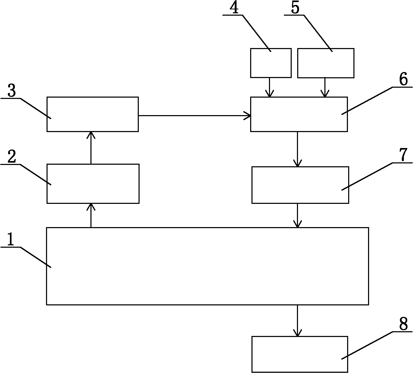
[0041] As shown in the drawings, the present invention discloses a system capable of controlling the viscosity of the electric spindle lubricating fluid, including an electric spindle 1, a monitoring module 2, a control module 3, a base fluid tank 4, a tackifier tank 5, and a liquid distribution module 6 , a liquid supply module 7 and a liquid return module 8 .

[0042] The monitoring module 2 is composed of various sensors, including a spindle load sensor, a speed sensor, a temperature sensor, a displacement sensor, etc., and each sensor monitors the spindle running indicators such as the load, speed, oil film thickness, oil film temperature, and axis trajectory of the electric spindle 1, and The monitoring signal is obtained, and then the monitoring signal is sent to the control module 3 .

[0043] Among them, the load sensor is used to monitor the load on the main shaft, and strain gauges, pressure sensors, etc. can be selected. The speed sensor is used to monitor the spee...


PUM


Abstract

The invention discloses a system capable of controlling the viscosity of electric spindle lubricant and a method thereof. The system comprises an electric spindle, a monitoring module, a control module, a base fluid box, a thickening agent box, a liquid distribution module, a liquid supply module and a liquid return module. The monitoring module is used for monitoring the operation condition of the electric spindle and transmitting a monitoring signal to the control module. The control module is used for operating the monitoring signal to obtain a lubricant viscosity value required in a current working condition, converting the monitoring signal into a viscosity control signal and transmitting the viscosity control signal to the liquid distribution module. The liquid distribution module is used for configuring the base fluid in the base fluid box and the thickening agent in the thickening agent box into the lubricant with the required viscosity according to the viscosity control signal. The liquid supply module is used for pressurizing the lubricant, filtering and inputting to the electric spindle. The liquid return module is used for recycling the lubricant. According to the system and the method disclosed by the invention, the viscosity of the lubricant can be controlled in real time according to working conditions; the working condition application range of the electric spindle is enlarged; the system and the method are applicable from a low speed to a high speed and from light load to heavy load, therefore, the electric spindle can be born and lubricated by the lubricant with the proper viscosity; and the operation stability is improved.

Description

technical field [0001] The invention relates to the technical field of electromechanical transmission equipment control, in particular to an electric spindle system and method capable of real-time control of lubricating fluid viscosity. Background technique [0002] CNC machine tools are developing in the direction of ultra-high speed and ultra-precision, and the machine tool spindle is the most critical component in CNC machine tools. The machine tool electric spindle integrates the spindle and the motor in structure, and has the advantages of low vibration and noise, wide speed range, quick start and accurate stop, etc. Among the current various spindle support methods, the hydrodynamic and static pressure support method is widely used in the field of high-speed precision machine tools because of its excellent high load capacity, high stiffness, high speed, high vibration damping, high rotation accuracy and long life. . Therefore, the spindle combined with the electric s...

Claims


Application Information

Patent Timeline
IPC IPC(8): G05D24/02B23Q11/12
Inventor 林彬闫帅刘峰
Owner TIANJIN UNIV
Why Eureka
Try Eureka