Method and device for the semi-active reduction of pressure oscillations in a hydraulic system

A hydraulic system, semi-active technology, applied in the direction of fluid pressure actuation device, fluid pressure actuation system component, rolling mill control device, etc., can solve the deterioration of system performance, the no longer compact power density of the actuator, and the stability of the overall system Sexual deterioration, etc.

Inactive Publication Date: 2014-06-11
SIEMENS VAI METALS TECHNOLOGIES GMBH & CO
View PDF7 Cites 0 Cited by
  • Summary
  • Abstract
  • Description
  • Claims
  • Application Information

AI Technical Summary

Problems solved by technology

This leads to actuators that are no longer compact (especially with a large volume) and only more advanced and expensive actuators can be used due to the high demands on power density
Another disadvantage of active oscillation compensation systems is the additional input of energy into the hydraulic system via actuators, which in principle degrades the stability of the overall system and can even lead to system performance especially if the regulator is not precisely adjusted Deterioration (that is, the amplitude of compression oscillations increases instead of falling)

Method used


Image

  • Method and device for the semi-active reduction of pressure oscillations in a hydraulic system
  • Method and device for the semi-active reduction of pressure oscillations in a hydraulic system
  • Method and device for the semi-active reduction of pressure oscillations in a hydraulic system

Examples


Embodiment Construction

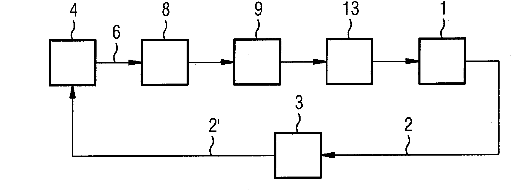
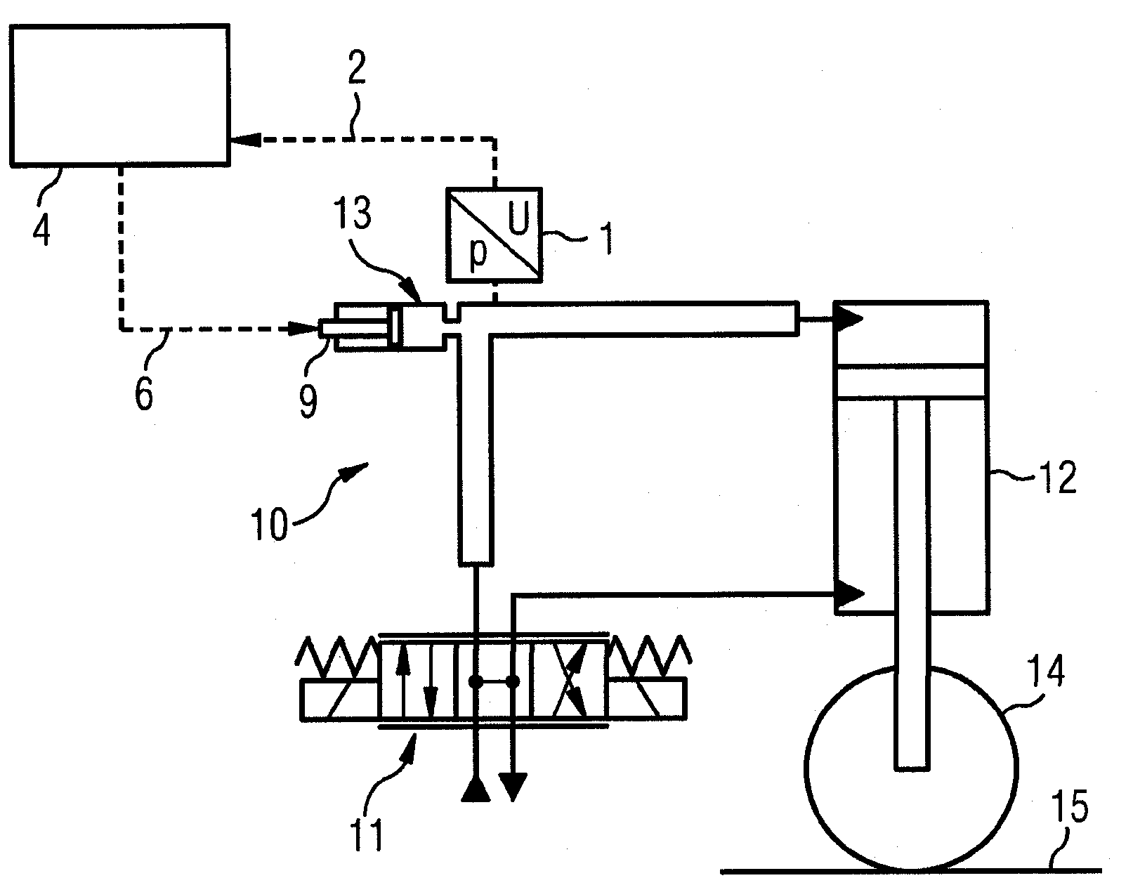
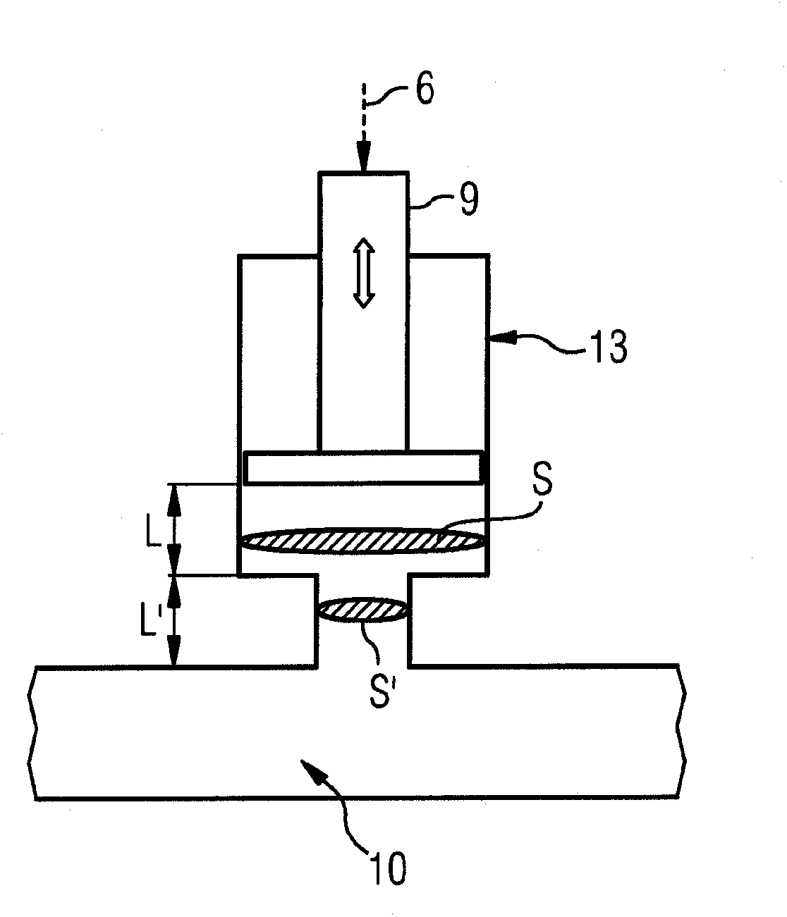
[0026] figure 1 The basic structure of the regulation path for reducing compression oscillations in the hydraulic system of a rolling mill is shown. The pressure signal of the pressure in the hydraulic system is detected by the pressure sensor 1, and the pressure signal 2 is sent to the high-pass filter 3 (for details of the electronic circuit, see, for example, page 35 of The Art of Electronics by P. Horowitz, W. Hill, Cambridge University Press, Second edition, 1989), the high-pass filter determines the AC component 2 ′ of the pressure signal 2 and supplies it to the regulator 4 . The controller 4 calculates a time-varying manipulated variable 6 in real time by means of a control law, taking into account the AC component 2 ′. The manipulated variable signal is then fed to an amplifier 8 , which activates an actuator 9 designed as an electric screw actuator. The resonator volume of the shock absorber 13 designed as a Helmholtz resonator is varied by the actuator 9 , wherein...


PUM


Abstract

A method and an apparatus for semiactive reduction of pressure oscillations in a hydraulic system of a cold or hot rolling mill or strip handling installation for iron, steel or aluminum materials has the following method steps in the stated sequence: a) detection of a pressure signal by a pressure sensor by permanent measurement of a pressure in the hydraulic system; b) determination of an alternating component of the pressure signal; c) determination of at least one manipulated variable, which varies over time, in real time with the aid of a regulator, taking account of the alternating component; d) application of the manipulated variable to at least one actuator, with the actuator changing a natural frequency of an oscillation damper which is connected to the hydraulic system, and thus reducing an amplitude of the pressure oscillations in the hydraulic system.

Description

technical field [0001] The invention relates to a method and a device for semi-active reduction of compression oscillations in a hydraulic system of a cold or hot rolling mill or strip processing plant for iron, steel or aluminum. Background technique [0002] Compression oscillations which occur periodically in hydraulic systems are known to cause various problems, such as excessive noise formation, reduced service life of components, disturbances in the control circuit, and the like. Compression oscillations are generated either within the hydraulic system itself, eg due to inhomogeneities in the delivery volume of the pumps or due to actuation of valves, etc., or externally, eg due to cyclical load changes of hydraulic cylinders or hydraulic motors. It is furthermore known that, especially in high-powered hydraulic systems, for example consisting of high-powered continuous hydraulic valves, such as electrically actuated proportional valves or servo valves, and hydraulic c...

Claims


Application Information

Patent Timeline
Patent Type & Authority Patents(China)
IPC IPC(8): B21B37/00
CPCB21B37/66B21B37/00B21B37/007F16L55/05B21B37/62F15B2211/6313F15B2211/8613F15B21/008
Inventor A·皮尔科G·凯因策尔
Owner SIEMENS VAI METALS TECHNOLOGIES GMBH & CO
Why Eureka
Try Eureka