A beam hanger, building frame structure and installation method

A technology of frame structure and hanging parts, which is applied in the direction of building structure, construction, and building material processing. It can solve the problems of reducing installation efficiency, increasing installation difficulty, and many connection links, and achieves improved utilization and aesthetics. Reduce excessive stress concentration and reduce the effect of connecting links

Inactive Publication Date: 2011-12-14
杨东佐
View PDF8 Cites 5 Cited by
  • Summary
  • Abstract
  • Description
  • Claims
  • Application Information

AI Technical Summary

Problems solved by technology

[0002] Existing cement brick mix, reinforced concrete house building and construction method thereof, owing to need to draw frame, cast concrete etc. with steel bar at the construction site, there is following shortcoming: the one is that its upright column pours and builds earlier, pours on upright column again Concrete floors are built, and the connection between the cement floor and the columns is mainly based on the steel bars on the columns and the cement floor. Since the columns and the cement floor are poured twice, the construction period is long, the labor intensity is high, the pollution is large, and the noise is large. The waste of construction raw materials is large; the second is that the relationship between two cement solids is only the bearing relationship of mechanical loads, and it is impossible to establish a truly integrated internal relationship, which has poor safety, poor earthquake resistance, and short service life; third, it is necessary to use cement, Wood and other building materials destroy ecology; Fourth, when houses are demolished, building materials cannot be reused, resulting in waste of resources and a large amount of construction waste that is difficult to handle; Fourth, due to the heavy weight of the frame structure of traditional cement buildings (high-rise buildings), The mechanical load of the foundation is very large. Once an earthquake shakes, the whole building becomes very fragile and dangerous, which is not conducive to earthquake resistance.
Second, there are many bolts and other fastening connections or welding connections on site, which will increase the difficulty of installation, reduce installation efficiency, and result in high labor and time costs for on-site construction.
The third is that the traditional building steel structure frame beams and columns or beams and beams are connected by bolt fastening or welding, and the respective connection ends must be designed and processed for matching connections. When standard profiles are used for beams or columns , the connecting ends must be designed and processed separately. When beams or columns do not use standard profiles, they need to be specially manufactured. Both methods cannot achieve mass standardized production. The cost is high, and beams or columns are prone to dimensional processing errors. The connection error makes it difficult for the already fragile connection position to bear the weight load of the building and the transmission of load force
Although in this technical scheme, the column member supports the lower column joint, the lower column joint supports the beam bucket, the beam bucket supports the upper column joint, the upper column joint supports the column member, and the beam bucket supports the beam bucket. It has a supporting function, and the gravity load of beams, columns, floors, etc. will no

Method used


Image

  • A beam hanger, building frame structure and installation method
  • A beam hanger, building frame structure and installation method
  • A beam hanger, building frame structure and installation method

Examples


Embodiment 1

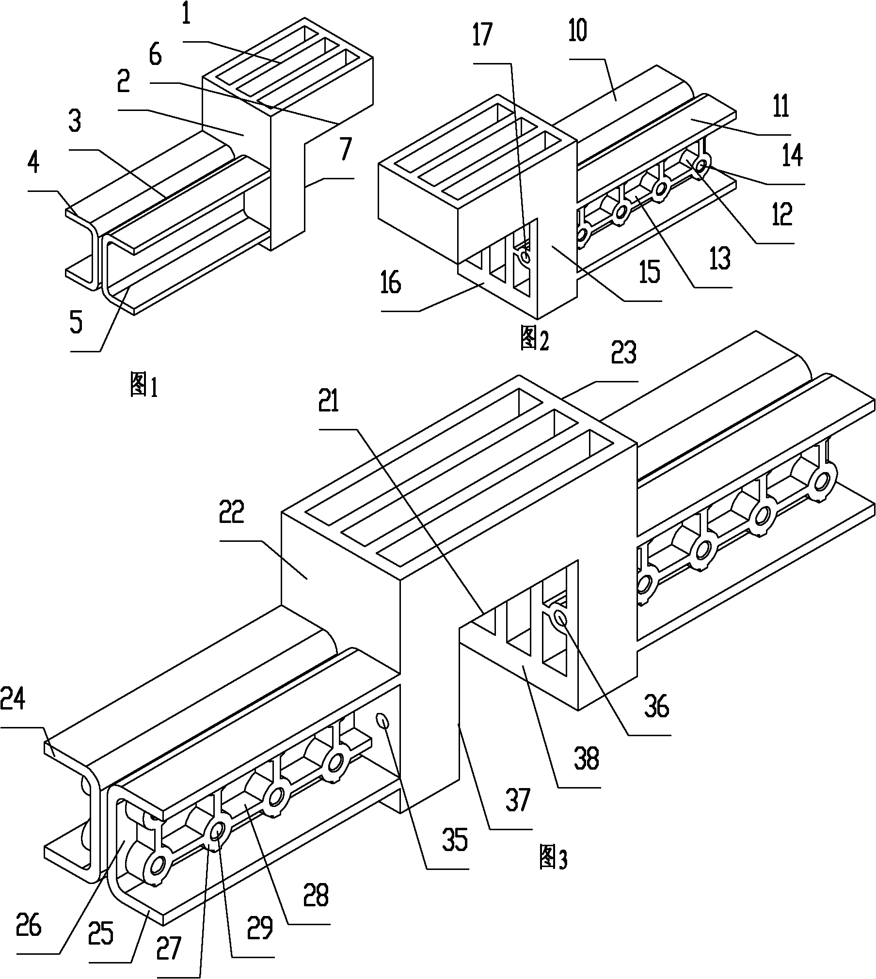
[0067] Such as figure 1 As shown, a beam hanger is a casting, including a block-shaped suspension part 1 supported on the beam, and a block-shaped connection part 2 extending downward from the bottom surface 6 of the vertical suspension part 1. On the side of the connecting part 2 facing away from the suspension part 1 , a beam plug connector 3 inserted into and plugged into the beam end. The beam plug joint 3 includes two symmetrical U-shaped blocks 4 and U-shaped blocks 5 extending vertically from the side of the connecting part away from the suspension part, with openings facing both sides horizontally side by side. The bottom surface 6 of the suspension part is directly The first supported surface supported on the beam; the vertical side 7 connected to the bottom surface 6 on the connecting part is the beam-side resisting surface resisted by the beam, and the beam-side resisting surface is located below the first supported surface.

Embodiment 2

[0069] Such as figure 2 Shown, different from embodiment 1, be provided with round platform 12 on the bottom plane of the U-shaped groove of U-shaped block 10, U-shaped block 11, be connected with reinforcing rib 13 between round platform 12, in each round platform A threaded through hole 14 is provided inside.

[0070] The connecting portion 15 is provided with a threaded through hole 17 which is vertical to the beam-side resisting surface 16 and communicates with the beam-side resisting surface 16 .

Embodiment 3

[0072] Such as image 3 As shown, a beam hanger includes a suspension part supported on the beam, and a symmetrical first connecting part and a second connecting part extending vertically downward from the bottom surface 21 of the hanging part are arranged at a position away from the hanging part On the side 22 of the first connecting part of the first connecting part, a first beam plug joint inserted into the beam end so as to be plugged with the beam end is arranged on the side 23 of the second connecting part away from the suspension part, inserted into the other beam end A second beam plug-in connection is thus plugged into the beam end.

[0073] The first beam plug connector includes two symmetrical U-shaped blocks 24 and 25 extending vertically from the side surface 22 and horizontally side by side with openings facing both sides. The bottom plane 26 of the U-shaped groove of the U-shaped block 24 is provided with circular platforms 27, and reinforcing ribs 28 are conne...


PUM


Abstract

A beam hanging component comprises a beam socket or a beam supporting joint, a hanging portion and a connection portion, all of which are formed integrally. A building frame structure comprises more than two beam hanging components, a beam with both ends fixed to the beam sockets or the beam supporting joints of the beam hanging components, and a beam onto which the hanging portions of the beam hanging components are directly supported and hung. A mounting method comprises the following steps of: firstly, inserting the two ends of the beam into the beam hanging components and movably connecting the beam to the beam hanging components; secondly, hanging the beam hanging components on the corresponding beams; thirdly, adjusting the relative positions of the beams and the beam hanging components; and finally, fixing the beam hanging components to the beams. The beam hanging component has the advantage that the connection between the beams can be completed conveniently and quickly.

Description

technical field [0001] The invention relates to a beam hooking piece for building, a frame structure and an installation method for the frame structure, in particular to a beam hooking piece, a beam frame structure and a method for installing the beam frame structure of a building frame steel structure. Background technique [0002] Existing cement brick mix, reinforced concrete house building and construction method thereof, owing to need to draw frame, cast concrete etc. with steel bar at the construction site, there is following shortcoming: the one is that its upright column pours and builds earlier, pours on upright column again Concrete floors are built, and the connection between the cement floor and the columns is mainly based on the steel bars on the columns and the cement floor. Since the columns and the cement floor are poured twice, the construction period is long, the labor intensity is high, the pollution is large, and the noise is large. The waste of construct...

Claims


Application Information

Patent Timeline
IPC IPC(8): E04B1/58E04B1/18E04G21/14
CPCE04B2001/249E04B2001/2421E04B1/24E04B2001/2451E04B2001/2457E04B2001/2448E04B2001/2406E04B2001/2463
Inventor 杨东佐
Owner 杨东佐
Why Eureka
Try Eureka