Pneumatic drill rig

A drilling rig and pneumatic technology, used in motor vehicles, crawler vehicles, earth-moving drilling, etc., can solve problems such as hidden safety hazards, not widely used, harsh operating environment, etc., achieve good synchronization and turning, improve safety, and operate safely. Effect

Inactive Publication Date: 2011-12-14
JIKAI HEBEI MECHATRONICS TECH CO LTD
View PDF4 Cites 8 Cited by
  • Summary
  • Abstract
  • Description
  • Claims
  • Application Information

AI Technical Summary

Problems solved by technology

Among them, pneumatic equipment uses compressed air as the power source, and is widely used due to its advantages of portability and low failure rate. Pneumatic equipment is divided into top bolter and support bolter according to different functions. Both types of bolter belong to hand-held drilling rigs. Workers need to directly overcome the counter torque of drilling to work. There are potential safety hazards in terms of human safety during the drilling process. At the same time, there are great limitations in the rotary power and drilling efficiency of the drilling rig. For example, the current top bolter is the largest The torque is only 140N.m, and the bolter is only 90N.m
In addition, because the workers are close to the power part of the drilling rig, the dust and flushing water from the drilling can directly splash on the human body

Method used


Image

  • Pneumatic drill rig
  • Pneumatic drill rig
  • Pneumatic drill rig

Examples


Example Embodiment

[0026] Specific embodiments according to the present invention will be described below with reference to the accompanying drawings.

[0027] Many specific details are set forth in the following description to facilitate a full understanding of the present invention. However, the present invention can also be implemented in other ways different from those described herein. Therefore, the present invention is not limited to the specific embodiments disclosed below. limit.

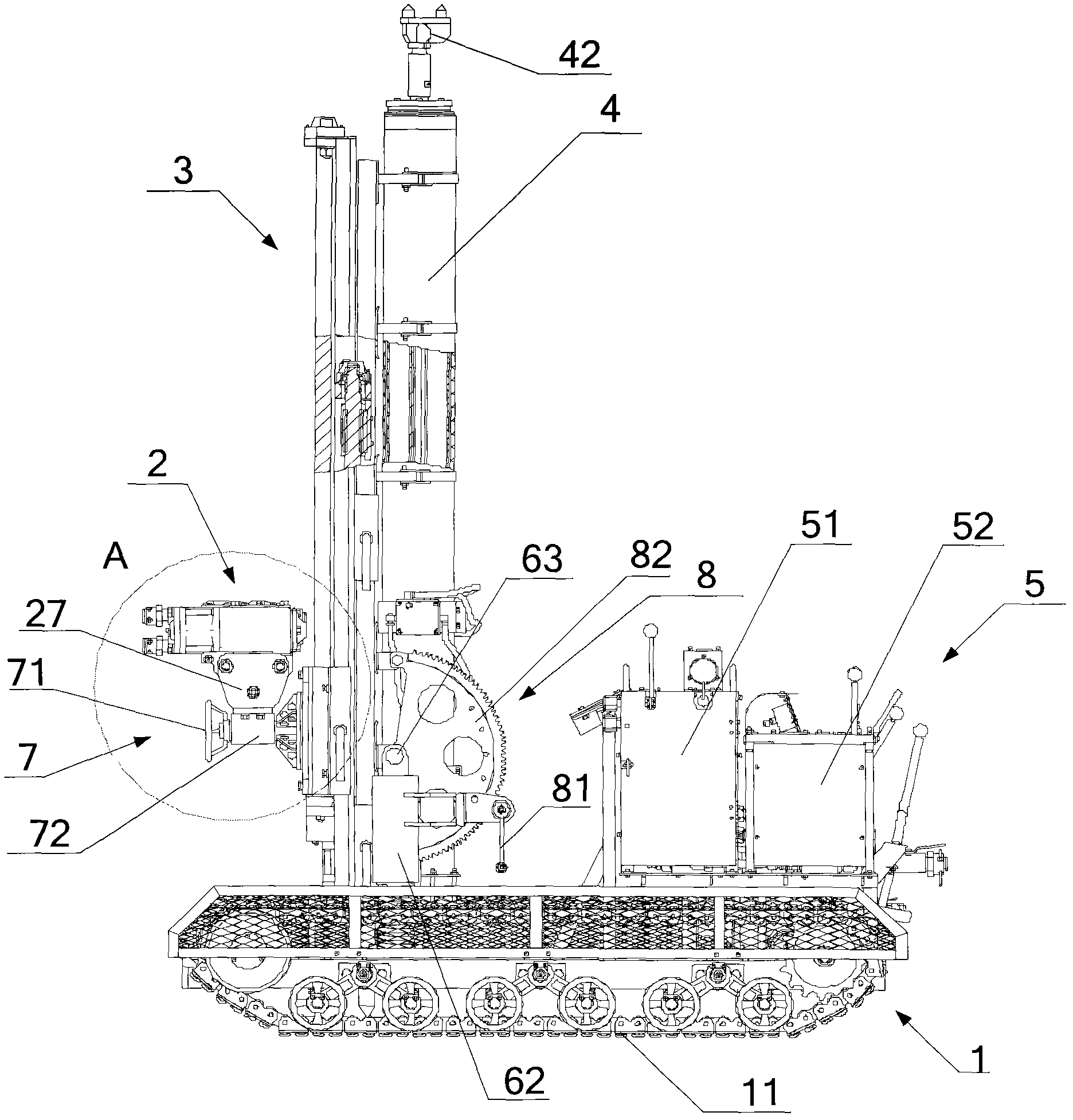
[0028] figure 1 A schematic diagram of the overall structure of a pneumatic drilling rig according to an embodiment of the present invention is shown.

[0029] like figure 1As shown, a pneumatic drilling rig provided by the present invention includes a traveling mechanism 1, a feeding and turning mechanism 2, a support column 4 and an operation console 5, and the operation console 5 and the support column 4 are installed on the walking On the mechanism 1, the feed rotation mechanism 2 is installed on the s...


PUM


Abstract

The invention provides a pneumatic wagon drill which comprises a travel mechanism, a feed rotary mechanism, a support upright column and an operating and control table, wherein the operating and control table and the support upright column are arranged on the travel mechanism, the feed rotary mechanism is arranged on the support upright column through an angle adjusting mechanism and a moving mechanism, the support upright column is arranged on the travel mechanism through a spring and can adjust an inclination angle of the support upright column through an inclination angle adjusting mechanism, and the feed rotary mechanism can move up and down along the support upright column through the moving mechanism and rotate in a working face through the angle adjusting mechanism. Owing to the technical scheme provided by the invention, the feed rotary mechanism of the pneumatic wagon drill can move rapidly with high efficiency, the jacking force and the drilling force are supported on the ground, the load on the travel mechanism is reduced, the service life of the pneumatic wagon drill is increased, and the manufacturing cost is reduced; and besides, the purpose of remotely controlling the drilling operation is achieved, the working environment is greatly improved, and the operating safety of workers is improved.

Description

technical field [0001] The invention relates to a pneumatic drilling vehicle, more specifically, to a fully pneumatic drilling vehicle for bolts used in underground coal mines. Background technique [0002] The drilling equipment of existing anchor rod, anchor cable hole mainly is divided into two classes: pneumatic equipment and hydraulic equipment. Among them, pneumatic equipment uses compressed air as the power source, and is widely used due to its advantages of portability and low failure rate. Pneumatic equipment is divided into top bolter and support bolter according to different functions. Both types of bolter belong to hand-held drilling rigs. Workers need to directly overcome the counter torque of drilling to work. There are potential safety hazards in terms of human safety during the drilling process. At the same time, there are great limitations in the rotary power and drilling efficiency of the drilling rig. For example, the current top bolter is the largest The...

Claims


Application Information

Patent Timeline
IPC IPC(8): E21B7/02E21B15/00E21B19/08E21B44/00B62D55/08
Inventor 高辉宋建锋侯忠良杨志国邓德磊
Owner JIKAI HEBEI MECHATRONICS TECH CO LTD
Why Eureka
Try Eureka