
dual clutch gearbox

A dual-clutch and gearbox technology, applied in the direction of instruments, controlled components, mechanical control devices, etc., can solve the problems of reduced service life of low-gear gears, damage of low-gear gears, and long power transmission routes, so as to improve the use of Effects of life, short transmission route, and reduced damage rate

Inactive Publication Date: 2011-12-14
SAIC MOTOR +1
View PDF5 Cites 12 Cited by
  • Summary
  • Abstract
  • Description
  • Claims
  • Application Information

AI Technical Summary

Problems solved by technology

However, in this dual-clutch gearbox, the four driving gears are sequentially arranged in the order of the third-speed driving gear, the first-speed driving gear, the second-speed driving gear and the fourth-speed driving gear, that is to say, the high gear The driving gear of the high gear is arranged at both ends of the input shaft, and the driving gear of the low gear is arranged in the middle of the input shaft. In the middle position of the input shaft, the rigidity of the system is poor, and the deformation of the shaft system is likely to cause damage to the low-gear gear, reducing the service life of the low-gear gear under high load
[0006] In the prior art, the oil pump for supplying oil to the dual-clutch gearbox is generally driven by a separate transmission shaft, which is directly connected to the output shaft of the engine. In this way, the power transmission route is long and the structure is complicated

Method used


Image

  • dual clutch gearbox
  • dual clutch gearbox
  • dual clutch gearbox

Examples


Embodiment Construction

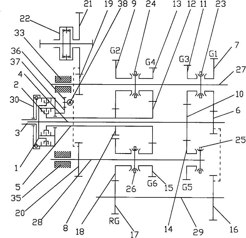
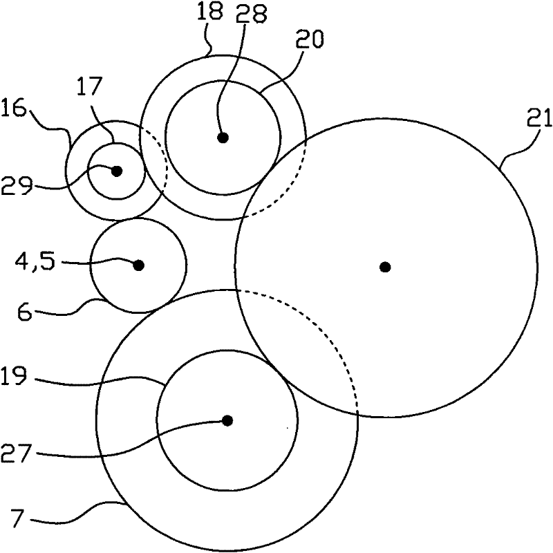
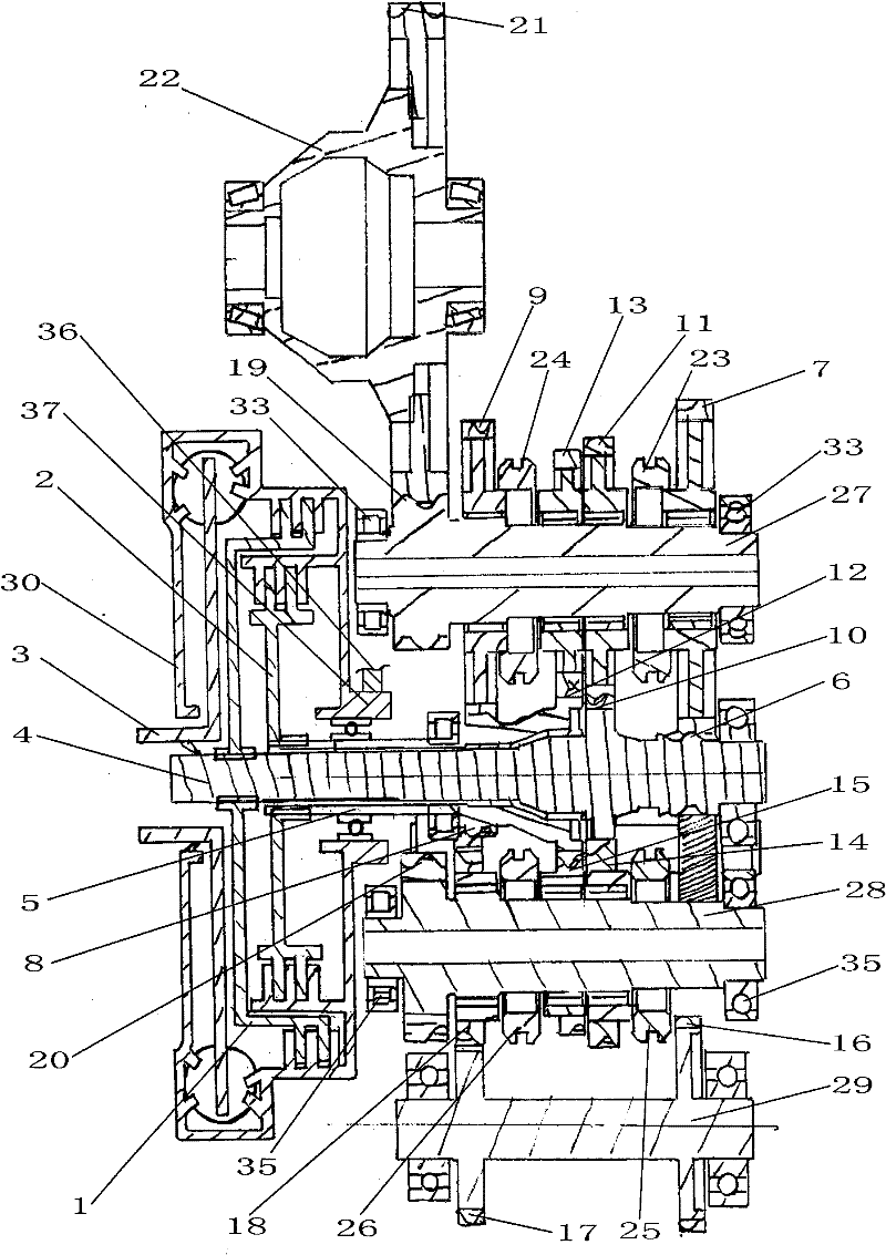
[0036] Such as figure 1 , image 3 As shown, the dual clutch gearbox of the present invention has two coaxially arranged input shafts 4 and 5 respectively connected to two clutches 1, 2 and the output shaft of the engine is connected to the clutch driving shaft 3. The torque of the engine It can be selectively transmitted to the inner input shaft 4 or the outer input shaft 5 through the two clutches 1 and 2. Among them, a first-speed driving gear 6 and a third-speed driving gear 10 are fixedly installed on the inner input shaft 4. The first-speed driving gear 6 is located at the rear end of the inner input shaft 4 (the end far from the engine); the outer input shaft 5 is fixedly installed with two The second-speed driving gear 8 is located at the front end of the outer input shaft 5 (close to the end of the engine), so that from the entire input shaft 4, 5, the second-speed driving gear 8 and the first The gear driving gear 6 is located on the front and rear sides, and the thi...


PUM


Abstract

The invention discloses a dual-clutch gearbox, which comprises inner and outer clutches, a clutch housing, two input shafts, two intermediate shafts and a reverse gear shaft, and the two input shafts are divided into inner input shafts arranged coaxially and the outer input shaft, the two input shafts are provided with driving gears for each gear, and the two intermediate shafts are provided with driven gears for each gear meshing with the driving gear, and the driving gear for the first gear and the driving gear for the second gear are located on all other gears. Both sides of the gear driving gear. In the present invention, the gears of the first gear and the second gear of the low-speed gear are respectively arranged at both ends of the shaft system. The advantage of this layout is that there are support bearings at both ends of the shaft system, and the system has better rigidity and can withstand the maximum load and traffic. The effect of variable torque. Equally, the driven gear of the reverse gear and the driven gear of the first gear share the driving gear of the first gear to resist the impact of bearing large loads and alternating torques during the reverse gear. It can reduce the damage rate of the gear caused by the deformation of the shaft system, and improve the service life of the low gear gear under high load.

Description

Technical field [0001] The invention relates to a dual-clutch gearbox, in particular to a structural arrangement of gears and shafts in the dual-clutch gearbox. Background technique [0002] At present, ordinary cars using traditional transmissions can only use 40% of the power potential under 80% of road conditions, and can only use 25% of the power potential under urban road conditions. Expert analysis shows that: AT (traditional hydro-mechanical automatic transmission) can automatically perform complicated functions such as acceleration, deceleration, and shifting. It has the advantages of smooth transmission and light driving, but its fuel consumption is 5% -15 higher than manual transmission. %; Although the CVT (Continuously Variable Transmission) has the characteristics of soft and comfortable speed ratio, the energy loss in the transmission is too large and does not save fuel, the load torque has limitations, and the manufacturing cost is high; AMT (automatic manual trans...

Claims


Application Information

Patent Timeline
IPC IPC(8): F16H3/093F16H3/12F16H63/32B60K17/06
CPCF16H3/006F16H2003/0931
Inventor 卢建钢黄明礼黄文华姜超张轶陈东海
Owner SAIC MOTOR
Learn More