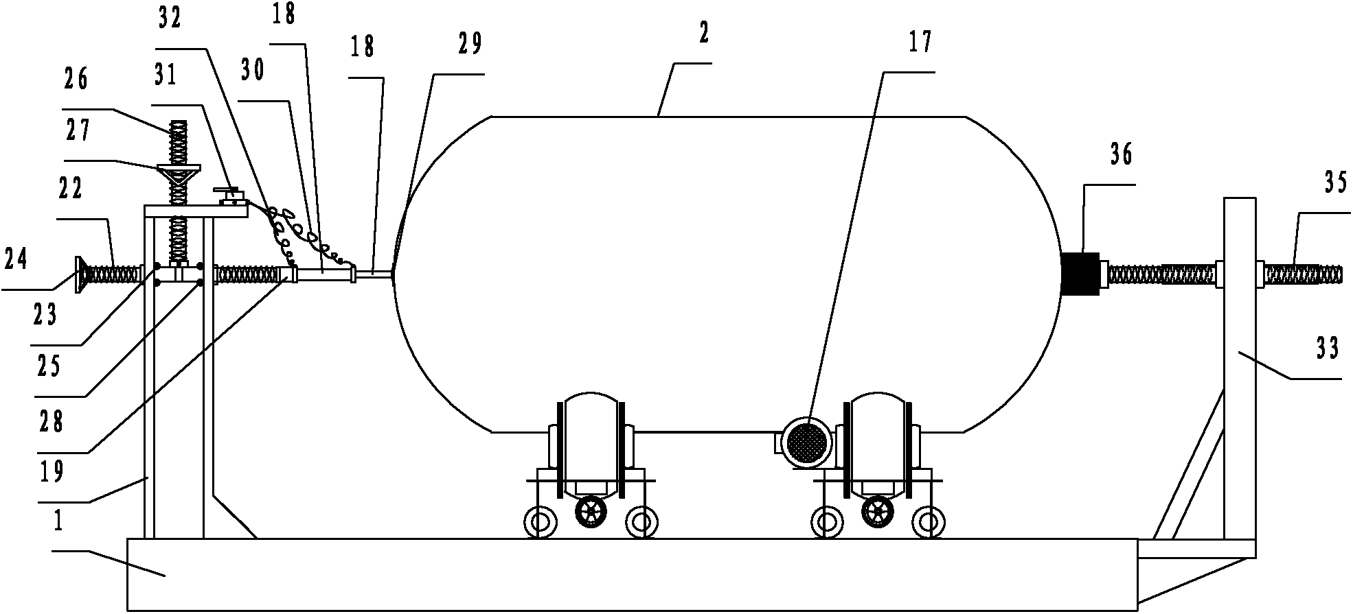
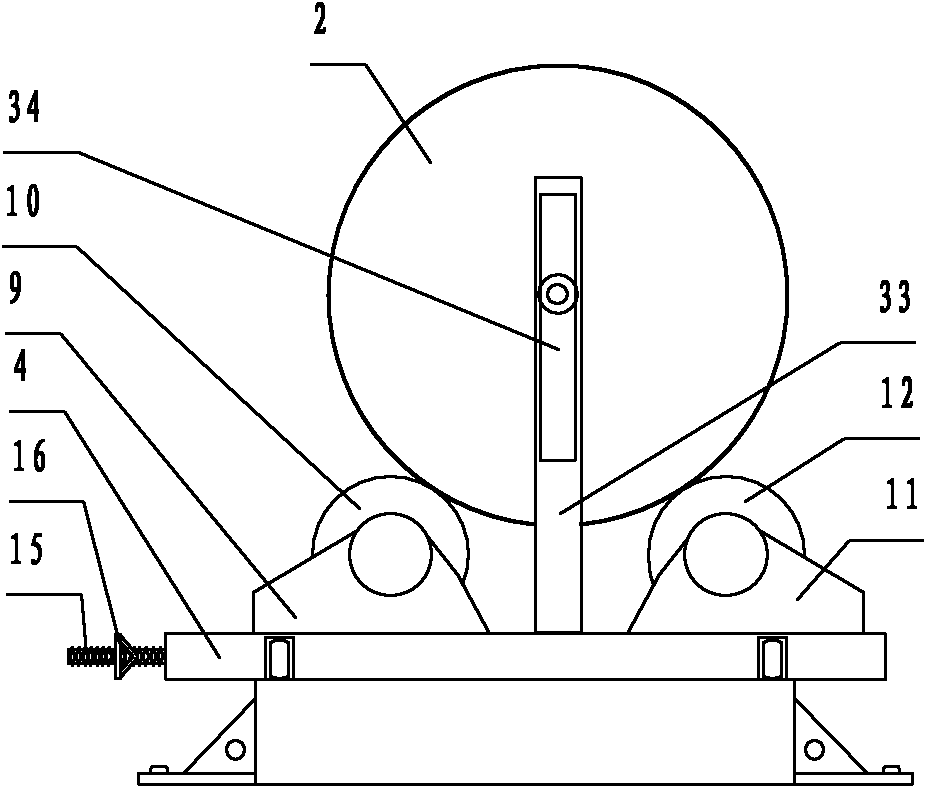
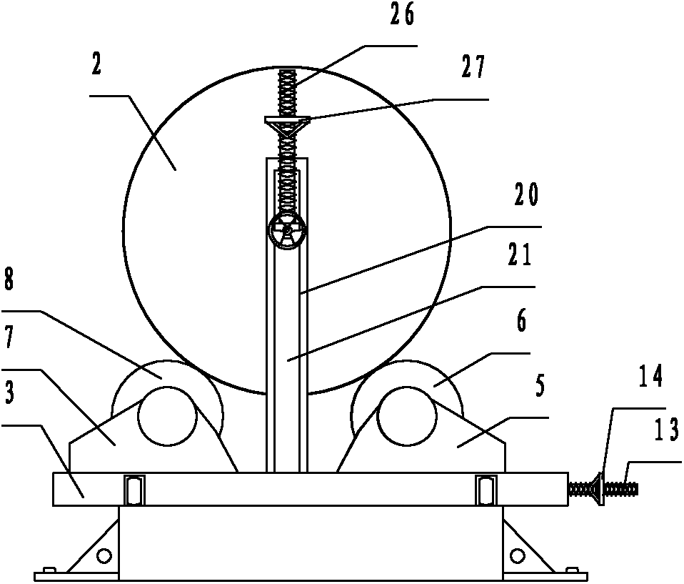
A positioning device for a welded tank body
A positioning device and tank body technology, applied in auxiliary devices, welding equipment, auxiliary welding equipment, etc., can solve the problem that the part clamped by the fixture cannot be welded, the positioner cannot clamp the tank body, and the welding quality of the weld seam is affected and other problems, to achieve the effect of not being easy to automatically shift, improving the pass rate of the tank body, and having a small clamping force
- Summary
- Abstract
- Description
- Claims
- Application Information
AI Technical Summary
Problems solved by technology
Method used
Image
Examples
Embodiment 2
[0042] Such as Figure 4 As shown, when different from Embodiment 1, a driving bearing 51 and a driving bearing 52 are installed under the left support frame 50, and the left supporting frame can move left and right on the base 53 through the driving bearing 51 and the driving bearing 52, and move to the desired position. Position, that is, after finding the position of the fixed tank body 54, the left support frame 50 is fixed on the base 53 by the driving positioning fixing screw clamp 55, so that the range of the tank body length that can be positioned is larger.
[0043] Such as Figure 5 As shown, it also includes a first ball bearing 57 and a first ball bearing 58 installed at the end of the piston rod 56, and a flexible suction cup 59 can be rotatably installed between the first ball bearing 57 and the first ball bearing 58 relative to the piston rod 56. The flexible suction cup 59 is fixed with the first ball bearing 57 and the first ball bearing 58 .
Embodiment 3
[0045] Such as Figure 5 As shown, the difference from Embodiment 2 is that a fourth screw driving motor 71 is installed on the fourth screw 70 , and a fifth screw driving motor 73 is installed on the fifth screw 72 .
[0046] The clamping mechanism on the right end face of the tank body includes a right support frame 74, a second threaded through hole (not shown) with a vertical straight line segment and a horizontal plane parallel to the right support frame 74, installed on the second threaded The second screw rod 76 on the through hole, two first bearings (not shown) installed on the second screw rod 76, the second screw rod drive motor 77, the lower end is installed on the second screw rod 76 and the third screw rod perpendicular to the horizontal plane 78, the upper end of the third screw rod 78 passes through the right support frame 74 and is screwed with the right support frame 74, is installed on the third screw rod 78 and is located on the third screw drive motor 79 a...
Embodiment 4
[0048] Such as Figure 6 As shown, different from Embodiment 2, the clamping mechanism on the left end surface of the tank body includes a left support frame 93, a fixed rod 91 installed on the left support frame 93, a sixth screw rod 92 whose lower end is fixed to the fixed rod 91, and a sixth screw rod 92 fixed to the fixed rod 91. The upper end of the screw rod 92 passes through the left support frame 93 and is threadedly engaged with the left support frame 93, and is installed on the sixth screw rod 92 and is positioned at the sixth adjusting handwheel 94 above the left support frame 93. The air cylinder 95 is fixed on the fixed rod 91 .
PUM
 Abstract
Description
Claims
Application Information
 - R&D
- Intellectual Property
- Life Sciences
- Materials
- Tech Scout
- Unparalleled Data Quality
- Higher Quality Content
- 60% Fewer Hallucinations
Browse by: Latest US Patents, China's latest patents, Technical Efficacy Thesaurus, Application Domain, Technology Topic, Popular Technical Reports.
© 2025 PatSnap. All rights reserved.Legal|Privacy policy|Modern Slavery Act Transparency Statement|Sitemap|About US| Contact US: help@patsnap.com


