Two-channel ultrasonic flowmeter time difference detection device

An ultrasonic flowmeter, ultrasonic flow technology, applied in measurement devices, test/calibration devices, liquid/fluid solids measurement, etc., can solve the problems of reduced signal strength, limited versatility, redesign, etc. The effect of great versatility and efficient detection

Inactive Publication Date: 2011-12-21
NAT INST OF METROLOGY CHINA
View PDF4 Cites 9 Cited by
  • Summary
  • Abstract
  • Description
  • Claims
  • Application Information

AI Technical Summary

Problems solved by technology

However, there are certain limitations in the use of this device: (1) It is difficult to accurately measure the length of the sound path
The standard time difference is calculated by the difference in the length of the sound channel. Since the time difference that usually needs to be detected is very small, reaching the order of microseconds, the measurement accuracy of the length is required to reach 0.1mm, or even 0.01mm. However, in this device, when the probe is installed It is impossible to directly measure the length of the acoustic path, and it is more difficult to measure the acoustic path length of the broken line formed by reflection; (2) It uses reflection and transmission to divide the ultrasonic signal into two paths, but because the signal strength is reduced by half, It may cause some flowmeters to be unable to receive signals; (3) the versatility is limited, because the probe must be sealed on the port of the liquid tank, the size and material of the probes of different manufacturers and models may be different, and the mechanical structure of the port needs to be redesigned; Its calibration control circuit needs to know the sending rules of the upstream and downstream probes of the ultrasonic flowmeter, otherwise the switching control of the transmitting and receiving ends cannot be realized, and each flowmeter manufacturer has its own sending rules, which are not the same

Method used


Image

  • Two-channel ultrasonic flowmeter time difference detection device
  • Two-channel ultrasonic flowmeter time difference detection device
  • Two-channel ultrasonic flowmeter time difference detection device

Examples


Embodiment Construction

[0021] In order to make the purpose, technical solution and advantages of the present invention clearer, the present invention will be further described in detail below with reference to the accompanying drawings and in combination with practical embodiments.

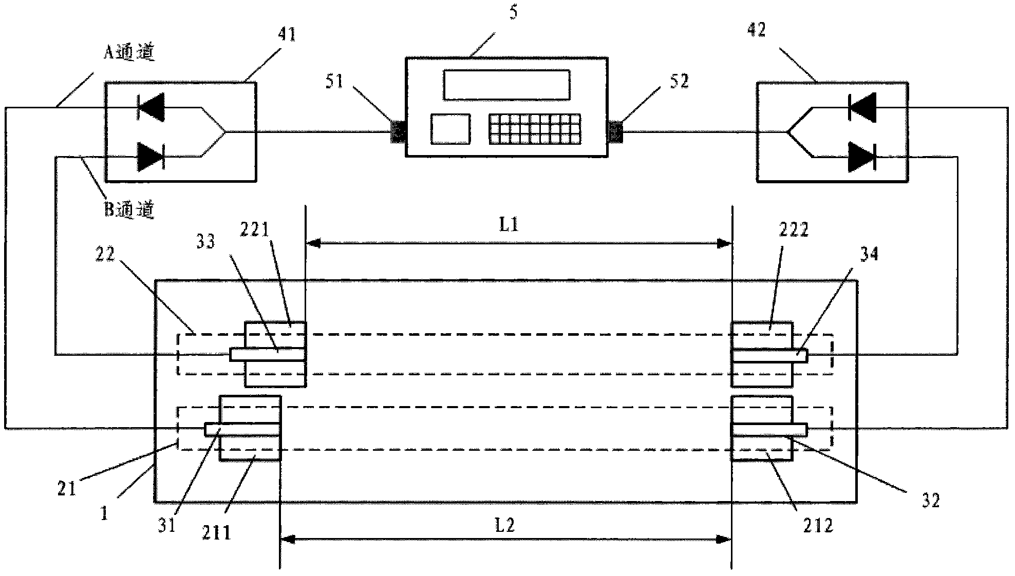
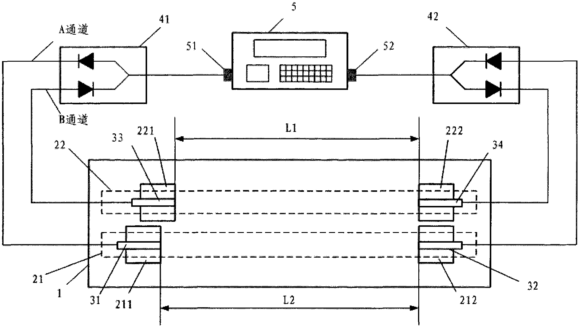
[0022] Such as figure 1 Shown is a schematic diagram of the structure of a two-channel time-of-flight ultrasonic flowmeter. The ultrasonic flowmeter forms two channels, A and B, and the flow velocity is obtained through the time difference between the two channels. Specifically, a liquid container is set in the measuring device, preferably the liquid container can be a liquid tank 1, in which there is a flowing liquid medium that can transmit ultrasonic signals, generally the same as the ultrasonic flowmeter measurement medium, the liquid medium There is a standard flow rate in the liquid tank, and its flow direction is relative to figure 1 It can be left or right, as long as the flow rate is stable and the flow direc...


PUM


Abstract

The invention provides a time difference detecting device of a dual-channel ultrasonic flow meter. The device comprises an ultrasonic flow meter to be detected, a first signal separating module connected with one end of the ultrasonic flow meter to be detected, a second signal separating module connected with the other end of the ultrasonic flow meter to be detected, and a first transducer, a second transducer, a third transducer and a fourth transducer which are located between the first signal separating module and the second signal separating module and arranged in a liquid container, wherein the first transducer and the second transducer are located in a first channel and the third transducer and the fourth transducer are located in a second channel. The detecting device provided by the invention has high universality and is applicable to flow meters of different manufacturers; and the device can realize quantity transmission by tracing to the source of geometric parameters and has high accuracy.

Description

technical field [0001] The invention relates to a detection device of an ultrasonic flowmeter, in particular to a flow velocity measurement and detection device of the ultrasonic flowmeter. The time difference and flow velocity measurement accuracy of the ultrasonic flowmeter can be detected and calibrated by using the device. Background technique [0002] Transit-time ultrasonic flowmeter is a speed-type flow measuring instrument with rapid technological development in recent years. It is widely used in natural gas flow, hydropower station flow, river flow, sewage flow and other measurement fields, and its measurement accuracy has attracted much attention. [0003] Ultrasonic flowmeters are widely used in the field of flow measurement, especially in large-diameter water flow (such as hydropower stations), natural gas flow, and open channel flow measurement, and have become the main measurement method. The accuracy of the flowmeter is often the technical index that users are...

Claims


Application Information

Patent Timeline
Patent Type & Authority Applications(China)
IPC IPC(8): G01F25/00
Inventor 孟涛胡鹤鸣张亮王池高峰
Owner NAT INST OF METROLOGY CHINA
Why Eureka
Try Eureka