Automatic Calibration Device and Calibration Method for Digital Vibration Meter

An automatic calibration and vibrometer technology, applied in measuring devices, instruments, measuring ultrasonic/sonic/infrasonic waves, etc., can solve the problems of high labor intensity, long calibration time, and low degree of intelligence

Active Publication Date: 2011-12-21
ZHEJIANG UNIV
View PDF3 Cites 15 Cited by
  • Summary
  • Abstract
  • Description
  • Claims
  • Application Information

AI Technical Summary

Problems solved by technology

[0004] In order to overcome the shortcomings of the prior art that require a large amount of manual intervention, high labor intensity, low degree of intelligence, and long calibration time, the present invention provides an

Method used


Image

  • Automatic Calibration Device and Calibration Method for Digital Vibration Meter
  • Automatic Calibration Device and Calibration Method for Digital Vibration Meter
  • Automatic Calibration Device and Calibration Method for Digital Vibration Meter

Examples


Embodiment 1

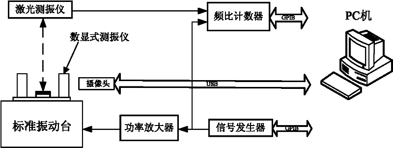
[0062] refer to figure 1 , 3 -7;

[0063] The automatic calibration device of the digital display vibrometer includes a signal generator whose amplitude and frequency of the output sinusoidal signal can be independently and continuously adjusted, a power amplifier connected to the signal generator, and a power amplifier connected to the power amplifier A connected standard vibrating table, a camera for recording the displayed value of the digital display vibrometer, a laser vibrometer for measuring the actual vibration level of the standard vibrating table, and a laser vibrometer for measuring the output signal of the laser vibrometer and the occurrence of the signal A frequency ratio counter that outputs the frequency ratio of the sinusoidal signal, and a processor; the calibrated digital vibrometer is installed on the standard vibration table.

[0064] Described processor is respectively connected with described signal generator, described video camera and described freque...

Embodiment 2

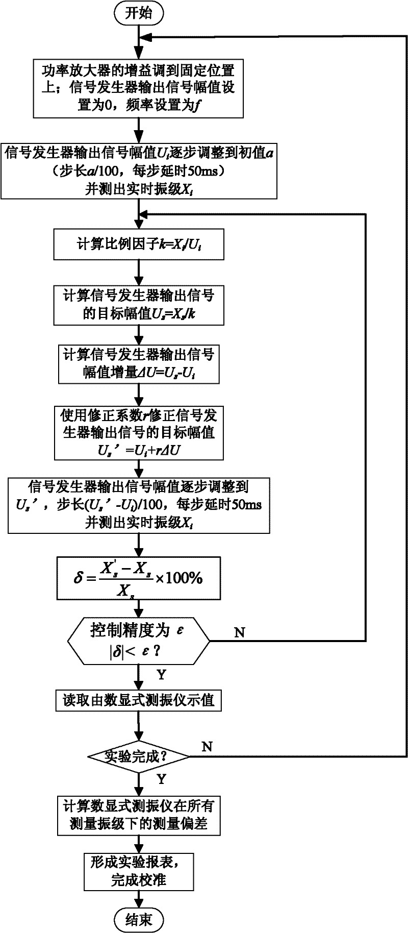
[0105] refer to figure 2

[0106] The method for calibrating the digital display vibrometer using the automatic calibration device of the digital display vibrometer includes the following steps:

[0107] 1), the gain of the power amplifier is adjusted to a predetermined position; the processor sets the amplitude of the output signal of the signal generator to 0, and the frequency is set to the specified value f in the test task list (thereafter remains unchanged);

[0108] 2), the signal generator output signal amplitude U i Increase to the initial value a, in order to prevent the increase of the output signal amplitude of the signal generator from impacting the standard vibration table, gradually increase the output amplitude of the signal generator with a / 100 as the step size, and delay 50ms per step , and then measure the real-time vibration level X of the standard shaking table i ;

[0109] 3), the real-time vibration level of the standard shaking table X i The measu...


PUM


Abstract

The invention discloses an automatic calibrating device of a digital display type vibration measurer, which comprises a signal generator, a power amplifier, a standard vibration table, a camera, a laser vibration measurer, a frequency ratio counter and a processor. A digital display type vibration measurer to be calibrated is mounted on the standard vibration table. The automatic calibrating method comprises the following steps of: adjusting the gain of the power amplifier to a predetermined position; increasing the amplitude Ui of an output signal of the signal generator to an initial value to measure the real-time vibration level of the standard variation table; measuring the real-time vibration level of the vibration table; adjusting the deviation of the vibration level to be smaller than the control precision of the vibration level; reading the vibration level of the standard vibration table measured by the digital display type vibration measurer by adopting an image recognizing method; judging whether a test is completed or not; and generating a test report form. The calibrating device and the calibrating method have the advantages that the calibration work of the digital display type vibration measure becomes simple and intelligent; the calibration time is shortened greatly; and the labor intensity is also lightened greatly.

Description

technical field [0001] The invention relates to an automatic calibration device and a calibration method for a digital display vibration measuring instrument. technical background [0002] With the development of science and technology, the requirements for the speed, load capacity, and working life of various rotating machinery and equipment are getting higher and higher, and people's understanding of vibration hazards is getting deeper and deeper. Therefore, in petroleum, chemical, electric power In industrial fields such as metallurgy and metallurgy, higher requirements are put forward for the on-site monitoring of mechanical equipment vibration. The digital display vibrometer is widely used in the on-site monitoring of rotating machinery vibration due to its advantages of low power consumption, high precision, high reliability, and convenient test and portability. [0003] According to the provisions of the National Metrology Verification Regulations (JJG 676-2000, Work...

Claims


Application Information

Patent Timeline
IPC IPC(8): G01H9/00
Inventor 何闻荣左超李根贾叔仕
Owner ZHEJIANG UNIV
Why Eureka
Try Eureka