Vehicle-mounted beehive frame device with mobile honey collection platform
A beehive rack and honey table technology, which is applied in the field of vehicle-mounted beehive rack devices, can solve the problems of large beehive integration, inconvenient occupied area, etc., and achieve the effects of reducing labor, saving time, and improving honey output.
- Summary
- Abstract
- Description
- Claims
- Application Information
AI Technical Summary
Problems solved by technology
Method used
Image
Examples
Embodiment 1
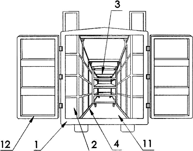
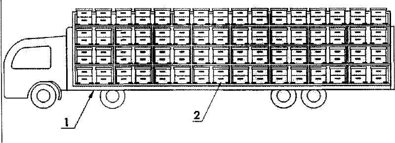
[0026] Embodiment 1: as Figure 1~3 As shown, a vehicle-mounted beehive frame device provided with a mobile honey collection platform includes a beehive frame 2 with a multi-layer frame structure arranged in the car compartment 1, the total height of the beehive frame 2 is 260cm, and the whole vehicle is equipped with 2 beehive frames , each beehive frame has 4 floors, each layer has 8 large grids, each large grid can place 2 standard beehives, each beehive frame can place a total of 64 standard beehives, and the two beehive frames of the whole vehicle can place a total of 128 beehives Standard beehive.
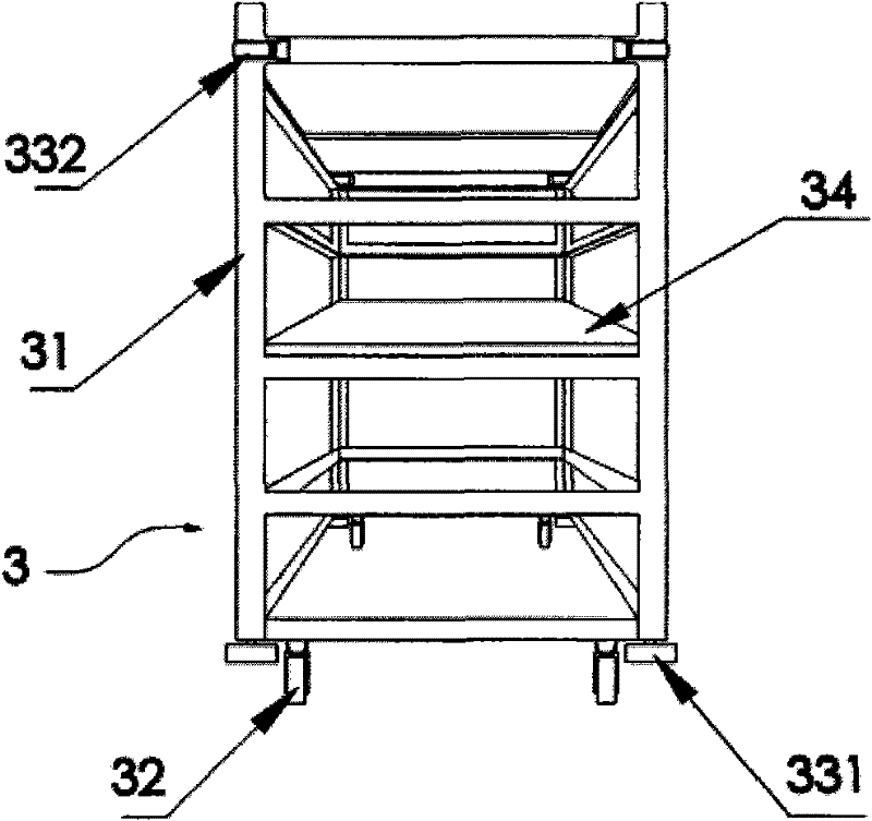
[0027] The beehive frame 2 is arranged according to the two sides of the carriage to form a roadway layout. The track and the mobile honey collecting rack are arranged in the roadway. The beehive nest opening on the outside of the compartment is free to enter and exit; the compartment bottom surface 11 next to the beehive frame 2 is provided with a mobile honey collection pl...
Embodiment 2
[0037] Embodiment 2: as Image 6 As shown, the platform 34 located on the support 31 is a liftable structure, and the traction motor 35 utilizes a worm and gear reduction mechanism 36 to change speed and drives the platform 34 by a rotating shaft 37 and a chain drive 38 along the cylindrical vertical guides located at both sides of the support. The column moves up and down, and the two ends of the rotating shaft 37 are connected with the bracket 31 by bearings. The power supply is provided by the vehicle battery; the moving distance of the platform 34 is controlled by a travel switch arranged on the support 31, and the locking of the working position of the platform is completed by an electromagnet traction block arranged on the support and interlocked with the travel switch.
PUM
 Abstract
Description
Claims
Application Information
 - R&D
- Intellectual Property
- Life Sciences
- Materials
- Tech Scout
- Unparalleled Data Quality
- Higher Quality Content
- 60% Fewer Hallucinations
Browse by: Latest US Patents, China's latest patents, Technical Efficacy Thesaurus, Application Domain, Technology Topic, Popular Technical Reports.
© 2025 PatSnap. All rights reserved.Legal|Privacy policy|Modern Slavery Act Transparency Statement|Sitemap|About US| Contact US: help@patsnap.com


