A method of making a cavity component using a mechanical mold system

A mechanical and cavity technology, which is applied in the field of making cavity components by using mechanical mold system, can solve the problems of low manual production efficiency, easy damage, high mold cost, etc., to improve production efficiency and social and economic benefits, and reduce production time , the effect of improving production efficiency

Inactive Publication Date: 2011-12-28
HUNAN BDF ENERGY SAVING TECH
View PDF6 Cites 20 Cited by
  • Summary
  • Abstract
  • Description
  • Claims
  • Application Information

AI Technical Summary

Problems solved by technology

[0004] However, because this technology still does not use mechanical production of cavity components, the geometric dimensions of the box produced by hand are prone to deviation and thickness, and the product density is not uniform. Cavity component products are not dense enough and prone to damage, and the inorganic gelling material of the hand-made cavity component needs to have certain fluidity and high water content, and the demoulding can only be done after the inor

Method used


Image

  • A method of making a cavity component using a mechanical mold system
  • A method of making a cavity component using a mechanical mold system
  • A method of making a cavity component using a mechanical mold system

Examples


Example Embodiment

[0026] The present invention will be further described below with reference to the accompanying drawings.

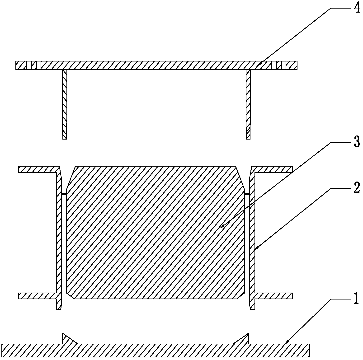
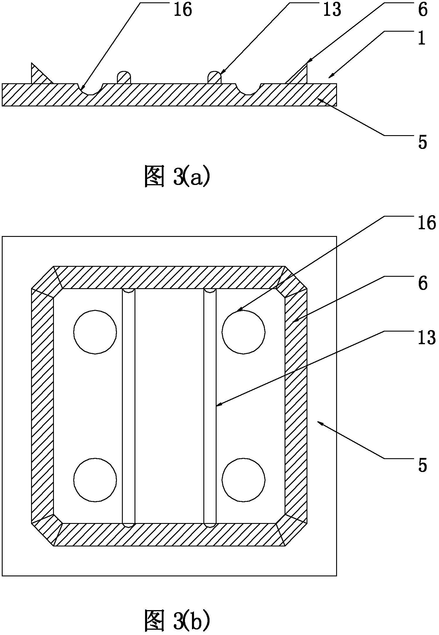
[0027] The technical solution of the present invention is a method for making a cavity member by using a mechanical mold system. Figures 1 to 7 The mechanical mold system adopted by this method invention is described in detail:

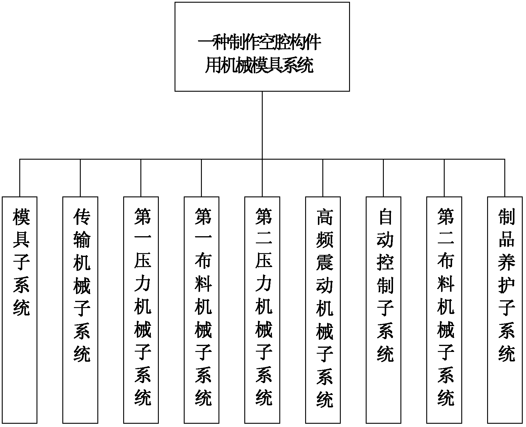
[0028] as attached figure 1 As shown, the mechanical mold system used in the present invention consists of a mold subsystem, a transmission mechanical subsystem, a first pressure mechanical subsystem, a first distribution mechanical subsystem, a second pressure mechanical subsystem, a high-frequency vibration mechanical subsystem, and automatic control subsystem.

[0029] The mold subsystem consists of a mold support device, an outer mold frame, an inner mold core and a split pressure ring. Wherein, the transmission mechanical subsystem is used to control the positioning and movement of the mold support device and the transport of the molded...


PUM


Abstract

The invention relates to a method for making a cavity member by using a mechanical die system. After the technical scheme is adopted, a die and a forming product are fast positioned and conveyed by a transport machine, the die is fast distributed by a distribution machine, a high-frequency vibrating machine keeps high-frequency vibration, cement in the die is fast and efficiently pressed and molded by adopting a high-strength hydraulic machine, and automatic operation of the machines is controlled by preset programs, so that full-automatic mechanical production of the cavity member is realized. By automatically controlled mechanical production in the method, the production time of the cavity member is reduced, and the production efficiency is improved; the pressure molded cavity member can be immediately stripped, so that the production and stripping time is shortened from 4 hours of manual production to about 1 minute; the pressure molded cavity member product is standard and has high density and strength and attractive appearance; and mechanical full-automatic production is realized, and the production efficiency and the social and economic benefits are greatly improved.

Description

technical field [0001] The invention relates to a method for making a concrete component by using a mechanical mold system, in particular to a method for making a cavity component by using a mechanical mold system in a cast-in-place cavity floor. Background technique [0002] At present, in the technical field of cast-in-place cavity floors, cavity floors are usually formed by casting cavity thin-walled box components, such as the ZL02282207.0 "thin-walled box embodied by the thin-walled box for pouring cavity panels" declared by the inventor. "Patent, the hollow wall of the thin-walled box produced according to this patent is thin, light in weight and high in strength. When it is applied to the cavity floor project, such as ZL200410082381.9 "a cavity with small ribbed floor" declared by the inventor, The cavity thin-walled box forms a hollow layer in the small ribbed floor, which can achieve the purposes of saving concrete for construction, reducing the height of the buildi...

Claims


Application Information

Patent Timeline
IPC IPC(8): B28B3/02B28B1/087
Inventor 王本淼王海崴
Owner HUNAN BDF ENERGY SAVING TECH
Why Eureka
Try Eureka