
A single crystal short rod splicing method using diamond wire cutting

A diamond wire and single crystal technology, which is applied in the field of single crystal short rod splicing using diamond wire cutting, can solve the problems of affecting the processing progress, consuming energy, and increasing the cost of working hours, so as to reduce processing costs, reduce process losses, and improve utilization. rate effect

Inactive Publication Date: 2011-12-28
江西金葵能源科技有限公司
View PDF10 Cites 24 Cited by
  • Summary
  • Abstract
  • Description
  • Claims
  • Application Information

AI Technical Summary

Problems solved by technology

[0002] In the growth of single crystal, the amount of feed, the control of crystal diameter, and the control of pot bottom material will all have an impact on the length of the crystal. In the fixed-length round rod, there will be a lot of residual material (short rod) that does not meet the fixed length. In addition, a certain amount of short rods will be produced when the edge is broken, so it is impossible to produce fixed-length silicon crystal rods according to our cutting requirements. After slitting to fixed lengths, a considerable proportion of stubs are produced
For the processing of short rods, one method at present is to return them to the furnace and remelt them. The second is to adjust the size of the wire cutting device. Remelting increases losses, consumes energy, increases man-hour costs, and increases use costs; adjust cutting process parameters and device, it will reduce the processing efficiency of the cutting machine, increase the cost of working hours, affect the processing progress, and is not conducive to large-scale processing

Method used


Image

  • A single crystal short rod splicing method using diamond wire cutting
  • A single crystal short rod splicing method using diamond wire cutting
  • A single crystal short rod splicing method using diamond wire cutting

Examples


Embodiment Construction

[0020] The following is a detailed description of the process of splicing single silicon crystal short rods into spliced ​​rods cut by diamond wire:

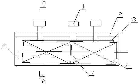
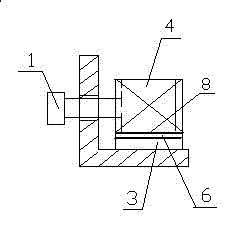
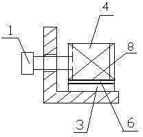
[0021] For the end face detection of short single silicon crystal rods, the flatness of the end face is required to be less than 0.3mm to ensure that the kerf is small; after passing the test, directly use AB glue to evenly spread on the end face, and bond the short rods to the round rods with a fixed length; for splicing rods Carry out square cutting, end face grinding, barrel grinding, and dimensional inspection. Design an L-shaped clamp with adjustment threads (such as figure 1 with figure 2 shown), the fixture is L-shaped, and it is composed of two rectangular plates at 90°, one rectangular plate is the bottom plate 5 and is set horizontally, and the other rectangular plate is the backing plate 2 and is vertically set, and the backing plate is set at intervals There is an adjusting screw 1, the axis of the adjusting screw...


PUM


Abstract

The invention discloses a single crystal short rod splicing method using diamond wire cutting. First, the end face of the single crystal silicon short rod is detected, and the flatness of the end face is required to be less than 0.3mm, and then the short rod is bonded by coating the end face with glue. After bonding, it is pressurized and solidified, and then the splicing rods are squared, end-face ground, and rolled. After passing the inspection, the splicing rods are cut into single-crystal silicon wafers in the slicing cabin. Make full use of all short monocrystalline silicon rods, greatly improve the utilization rate of short monocrystalline silicon rods, and reduce production costs. Since the splicing rods are not perpendicular to the diamond wire, the diamond wire does not need Adjusting the position of the wire cutting device can make the diamond wire never appear empty when cutting the splicing rod. The splicing rod method of the present invention can make full use of the single crystal silicon short rod to be processed into silicon wafers, which improves the round silicon The utilization rate of rods reduces the processing cost.

Description

technical field [0001] The invention belongs to a method for splicing silicon crystal rods by using diamond wire-cut single crystals in the photovoltaic industry. Background technique [0002] In the growth of single crystal, the amount of feed, the control of crystal diameter, and the control of pot bottom material will all have an impact on the length of the crystal. In the fixed-length round rod, there will be a lot of residual material (short rod) that does not meet the fixed length. In addition, a certain amount of short rods will be produced when the edge is broken, so it is impossible to produce fixed-length silicon crystal rods according to our cutting requirements. After slitting to fixed lengths, a considerable proportion of stubs are produced. For the processing of short rods, one method at present is to return them to the furnace and remelt them. The second is to adjust the size of the wire cutting device. Remelting increases losses, consumes energy, increases m...

Claims


Application Information

Patent Timeline
Patent Type & Authority Applications(China)
IPC IPC(8): B28D5/04
Inventor 于景俞建业曾斌叶平欧阳思周汤玮胡凯
Owner 江西金葵能源科技有限公司
Learn More