High-precision speed locker for multi-span bridge anti-seismic

A speed-locking, high-precision technology, applied in bridges, bridge parts, bridge construction, etc., can solve the problems of low horizontal strength of multi-span bridges, achieve high sensitivity, enhanced sealing effect, and good reversibility

Inactive Publication Date: 2011-12-28
UNIV OF SCI & TECH OF CHINA
View PDF4 Cites 15 Cited by
  • Summary
  • Abstract
  • Description
  • Claims
  • Application Information

AI Technical Summary

Problems solved by technology

[0004] In order to solve the shortcomings of low horizontal strength of multi-span bridges, this invention provides a high-precision speed l

Method used


Image

  • High-precision speed locker for multi-span bridge anti-seismic
  • High-precision speed locker for multi-span bridge anti-seismic
  • High-precision speed locker for multi-span bridge anti-seismic

Examples


Embodiment 1

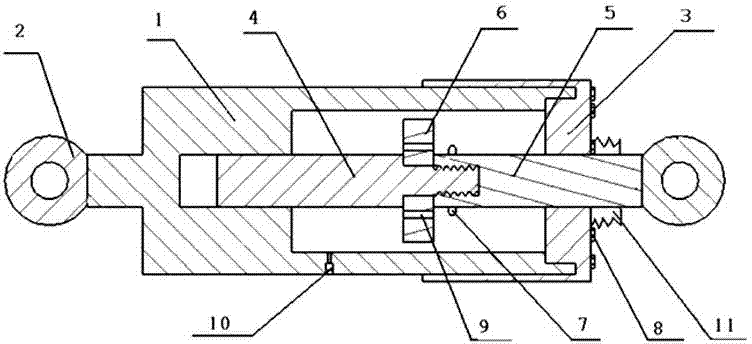
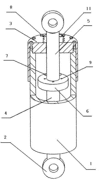
[0025] see figure 1 with figure 2 , The multi-span bridge anti-seismic high-precision speed locker includes a cylinder part, a piston part and a working material, the piston part and the cylinder part are assembled to form a whole, the working material is located in the cylinder, and the working material is a shear thickening fluid. The cylinder body part includes a cylindrical cylinder body 1 and an end cover, and a connecting seat 2 is installed at the outer end of the cylinder body 1 . The piston part includes a piston 6, a piston rod 4 and a connecting rod 5, one end of the piston rod 4 and one end of the connecting rod 5 are threadedly connected, and the other end of the connecting rod 5 extends outside the other end of the cylinder. The piston 6 is sleeved on the piston rod 4 , and the piston 6 is provided with an anti-skid bump 7 and a damping hole 9 .

[0026] The end cover is a cylindrical sealing cover 3, which is connected to the cylinder body 1 by bolts 8. The b...

Embodiment 2

[0029] see figure 1 with figure 2 , A dust cover 11 is installed on the outer side of the sealing cover 3, and the dust cover 11 is sleeved on the connecting rod 5.

[0030] The working material is a shear thickening gel.

[0031] Other structures are with embodiment 1.

[0032] In a dusty environment, installing the dust cover 11 on the high-precision speed locker can effectively prevent dust from entering the cylinder cavity, and prevent dust from reducing the performance of the shear thickening material.

Embodiment 3

[0034] The difference with Example 1 is:

[0035] A liquid injection hole 10 is provided on the side wall of the cylinder body 1. The diameter of the liquid injection hole is 6 mm, and a plunger is installed in the liquid injection hole 10 . See figure 2 . If the high-precision speed locker is used for a long time, liquid leakage will inevitably occur, resulting in a decrease in accuracy. At this time, the shear thickening material can be injected into the cylinder through the liquid injection hole 11 .


PUM

PropertyMeasurementUnit
Axial lengthaaaaaaaaaa
Diameteraaaaaaaaaa
Axial lengthaaaaaaaaaa

Abstract

The invention relates to a high-precision speed locker for anti-seismic use of multi-span bridges. Including the cylinder part, the piston part and the working material; the piston part and the cylinder part are assembled to form a whole, and the working material is located in the cylinder; the working material is a shear thickening liquid or a shear thickening gel; the cylinder body The end cover is a cylindrical sealing cover, and the bottom of the sealing cover is provided with a boss matching the inner diameter of the cylinder; the outer side of the sealing cover is provided with a dust cover; the piston rod and the connecting rod are threaded ; A liquid injection hole is opened on the side wall of the cylinder body, and a plunger is arranged in the liquid injection hole. The shear thickening liquid and shear thickening gel used in the present invention are very soft at ordinary times and have easy flowability under normal conditions. Once the critical shear rate is reached, the viscosity increases rapidly and finally becomes a hard solid. Return to the soft state; make the speed locker have the characteristics of precision, high sensitivity, and good reversibility.

Description

technical field [0001] The invention belongs to the field of anti-seismic technology of bridges, and in particular relates to a speed locker which has reinforcement and anti-seismic capabilities and can limit the moving speed within a certain range. Background technique [0002] In recent years, inevitable natural disasters such as earthquakes, tsunamis, and typhoons have occurred frequently, seriously threatening the safety of people's lives and property. Especially bridges, viaducts and these large buildings will lose immeasurable losses once they are damaged. Multi-span bridges are one of the common bridges. In order to reduce the influence of temperature during the design and construction process, the main girder is generally supported on the pier. Such structures are often damaged by the above-mentioned natural disasters due to insufficient horizontal strength. [0003] The speed locker is a piston-type cylindrical cavity structure device. When the piston and the cyl...

Claims


Application Information

Patent Timeline
IPC IPC(8): E01D19/00E04B1/98
Inventor 龚兴龙蒋伟峰徐钰蕾江万权孙英强
Owner UNIV OF SCI & TECH OF CHINA
Why Eureka
Try Eureka