Method for detecting microstructure of reverse osmosis membrane separating layer

A technology of reverse osmosis membrane and microstructure, applied in semi-permeable membrane separation, chemical instruments and methods, membrane technology, etc., can solve the problem of inability to detect the section of the separation layer and the microstructure of its back surface, and achieves easy promotion and low equipment requirements. , the effect of strong practicability

Inactive Publication Date: 2013-03-27
TIANJIN SEA WATER DESALINATION & COMPLEX UTILIZATION INST STATE OCEANOGRAPHI
View PDF3 Cites 0 Cited by
  • Summary
  • Abstract
  • Description
  • Claims
  • Application Information

AI Technical Summary

Problems solved by technology

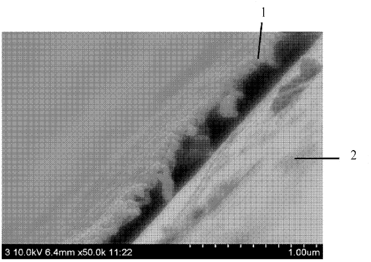
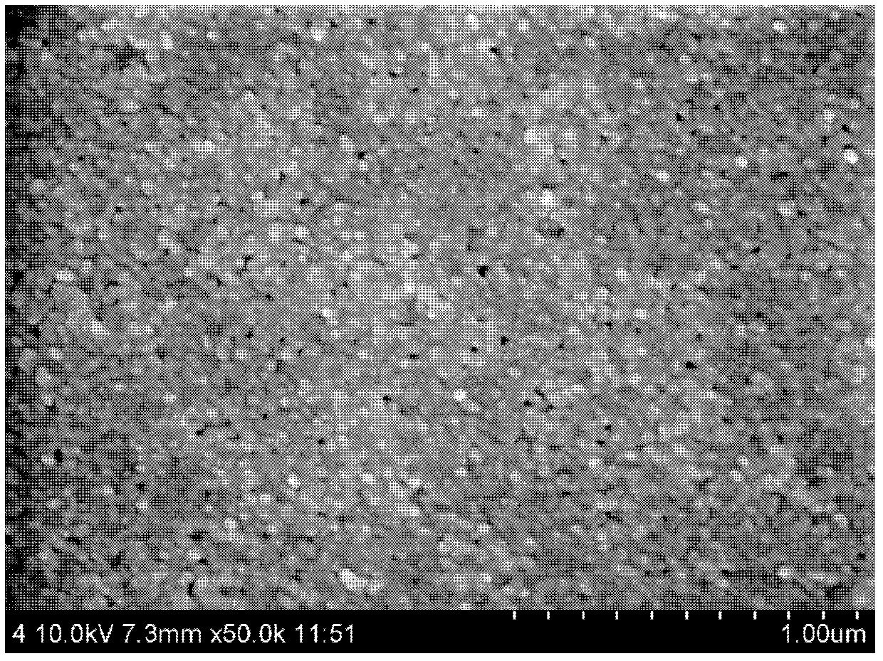
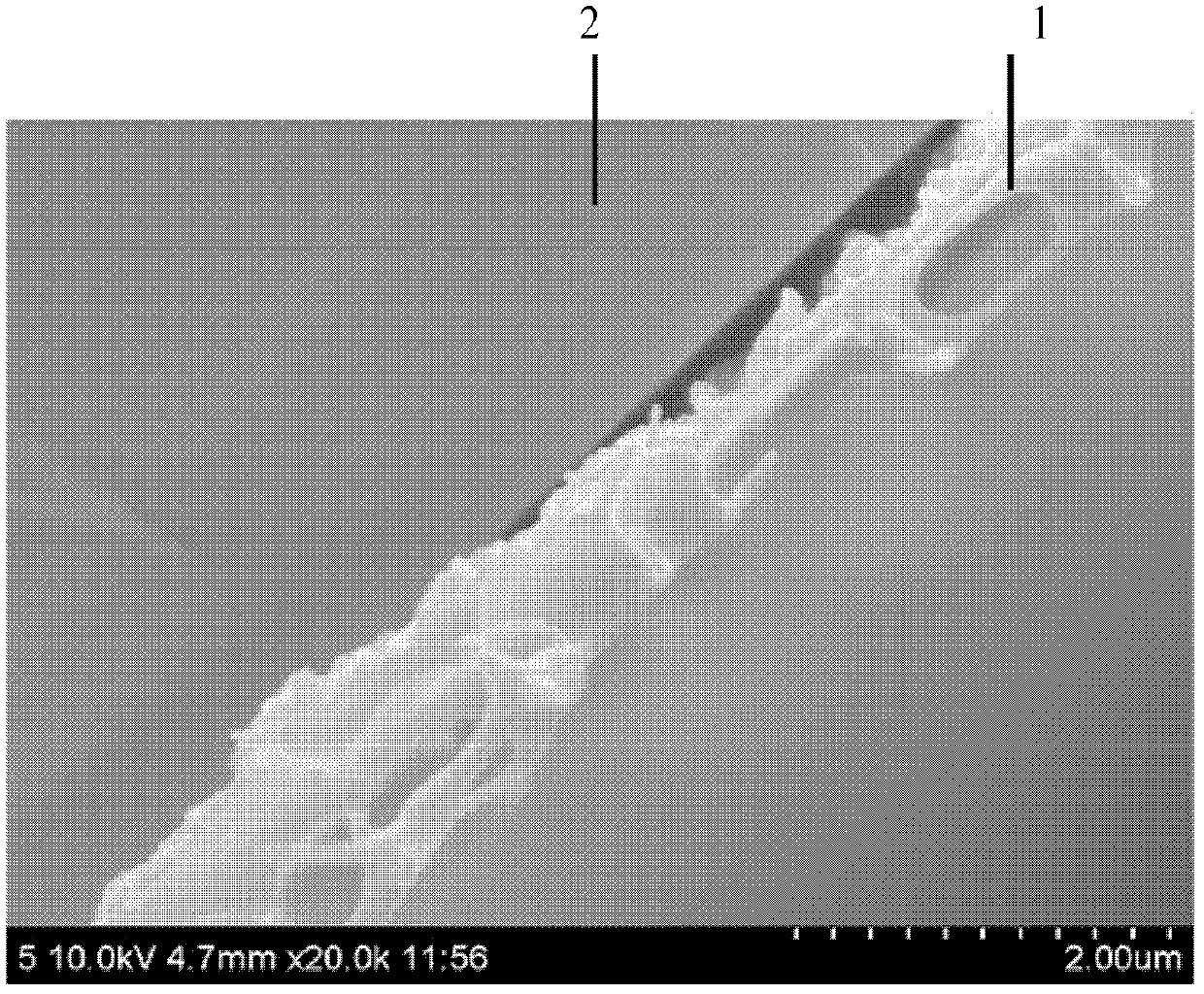
[0005] What the present invention aims to solve is the deficiency of the microstructure detection of the separation layer of the reverse osmosis membrane at present, that is, the technical problem that the cross section of the separation layer and the microstructure of the back side cannot be detected, and a field emission scanning electron microscope can be used to clearly observe the separation layer of the reverse osmosis membrane. The detection method of cross-section and back microstructure has simple sample pretreatment process, low cost, strong operability, and is easy to popularize. It fills the blank of using scanning electron microscope to observe the cross-section and back microstructure of reverse osmosis membrane separation layer at home and abroad.

Method used


Image

  • Method for detecting microstructure of reverse osmosis membrane separating layer
  • Method for detecting microstructure of reverse osmosis membrane separating layer
  • Method for detecting microstructure of reverse osmosis membrane separating layer

Examples


Embodiment 1

[0034] A 20mm×20mm low-pressure reverse osmosis membrane A is taken from the LP21 reverse osmosis membrane produced by Beijing Times Wharton Technology Co., Ltd.

[0035] Use tweezers to peel off the non-woven fabric layer of reverse osmosis membrane A, keep the separation layer and support layer, and paste it on the cover glass with the same size of 20mm×20mm with double-sided tape, so that the support layer faces On, place the separation layer in direct contact with the coverslip. In this way, it is ensured that in the process of washing and dissolving the supporting layer with an organic solvent, the organic solvent can directly contact with the supporting layer, so that the polysulfone supporting layer can be completely removed.

[0036] The coverslips were washed with distilled water and ethanol before use, and dried to remove surface-adhered pollutants. According to the difference in solubility between the separation layer and the support layer, a suitable volatile orga...

Embodiment 2

[0040] A 45mm×26mm ultra-low pressure reverse osmosis membrane B is taken from the ULP21 type reverse osmosis membrane produced by Beijing Times Wharton Technology Co., Ltd.

[0041] Use tweezers to peel off the non-woven fabric layer of reverse osmosis membrane B, keep the separation layer and support layer, and paste it on the cover glass with the same size of 45mm×26mm with double-sided tape, so that the support layer faces On, place the separation layer in direct contact with the coverslip. In this way, it is ensured that in the process of washing and dissolving the supporting layer with an organic solvent, the organic solvent can directly contact with the supporting layer, so that the polysulfone supporting layer can be completely removed.

[0042]The coverslips were washed with distilled water and ethanol before use, and dried to remove surface-adhered pollutants. According to the difference in solubility between the separation layer and the support layer, a suitable vo...

Embodiment 3

[0046] A pollution-resistant reverse osmosis membrane C of 25mm×75mm was taken. The pollution-resistant reverse osmosis membrane C was taken from the FR11 reverse osmosis membrane produced by Beijing Times Wharton Technology Co., Ltd.

[0047] Use tweezers to peel off the non-woven fabric layer of reverse osmosis membrane C, keep the separation layer and support layer, and paste it on a glass slide with the same specification of 25mm×75mm with double-sided tape, so that the support layer faces On, place the separation layer in direct contact with the glass slide. In this way, it is ensured that in the process of washing and dissolving the supporting layer with an organic solvent, the organic solvent can directly contact with the supporting layer, so that the polysulfone supporting layer can be completely removed.

[0048] The coverslips were washed with distilled water and ethanol before use, and dried to remove surface-adhered pollutants. According to the difference in solub...


PUM


Abstract

The invention discloses a method for detecting a microstructure of a reverse osmosis membrane separating layer. The method comprises the following steps of: completely peeling a non-woven layer of a reverse osmosis membrane sheet; remaining a separating layer and a supporting layer and flatly paving the separating layer and the supporting layer on a glass sheet and adhering the separating layer and the supporting layer to the glass sheet, so that the supporting layer is upward and the separating layer contacts with the glass sheet; according to the solubility difference between the separating layer and the supporting layer, dissolving and removing the supporting layer by selecting a proper volatile organic solvent; removing the organic solvent from the separating layer through vacuum drying; cutting the glass sheet with the separating layer into small blocks according to the size of a scanning electronic microscope sample platform; spraying gold; and observing the microstructures of the reverse side and the section of the separating layer by using a field emission scanning electronic microscope. By the method, the microstructures of the reverse side and the section of the separating layer of the reverse osmosis membrane can be observed clearly. The method is simple in pretreatment process of samples, low in cost, high in operability and easy in popularization. By the method, the microstructures of the reverse side and the section of the separating layer of the reverse osmosis membrane can be observed by using the scanning electronic microscope at home and abroad.

Description

technical field [0001] The invention relates to a method for detecting the microstructure of the separation layer of a reverse osmosis membrane, in particular to a method for detecting the microstructure of the cross section and the back surface of the separation layer of the reverse osmosis membrane. Background technique [0002] Reverse osmosis membranes are widely used in seawater and brackish water desalination, water purification, biomedicine, chemical industry and other fields. The current commercial reverse osmosis membrane usually consists of three layers: separation layer, support layer and non-woven fabric. The separation layer is mainly made of aromatic polyamide material, and the support layer is usually porous polysulfone material. The separation layer is the main functional layer of the reverse osmosis membrane. The thickness of its cross-section is related to the microscopic morphology, the microscopic morphology of the front and back (that is, the surface in ...

Claims


Application Information

Patent Timeline
Patent Type & Authority Patents(China)
IPC IPC(8): B01D65/10
Inventor 李强潘献辉侯纯扬
Owner TIANJIN SEA WATER DESALINATION & COMPLEX UTILIZATION INST STATE OCEANOGRAPHI
Why Eureka
Try Eureka