Machine-made die for making combined cavity member

A mechanism and mold technology, which is applied in the field of mechanism molds for making combined cavity components, can solve problems such as easy damage, high mold cost, and easy to produce deviation thickness, etc., to achieve the effects of reducing production time, improving production efficiency, and beautiful appearance

Inactive Publication Date: 2013-08-07
HUNAN BDF ENERGY SAVING TECH
View PDF3 Cites 0 Cited by
  • Summary
  • Abstract
  • Description
  • Claims
  • Application Information

AI Technical Summary

Problems solved by technology

However, because this technology still does not use mechanical production of cavity components, the geometric dimensions of the manually produced boxes are prone to deviations and uneven thickness, and the product density is uneven. The inorganic gelling material of the cavity component needs to have certain fluidity and high water content, and the demoulding cannot be done until the inorganic gelling material undergoes curing reaction and condensation. The utilization period of a set of molds is more than 4 hours, and the mold and site occupy a large amount. , the cost of the mold is high, the efficiency of manual production is low and the speed is slow, it cannot form large-scale industrial production, and it cannot meet the booming hollow floor market for hollow components-thin-walled boxes, and cannot meet the industrial production of cavity components requirements

Method used


Image

  • Machine-made die for making combined cavity member
  • Machine-made die for making combined cavity member
  • Machine-made die for making combined cavity member

Examples


Embodiment Construction

[0023] The present invention will be further described below in conjunction with accompanying drawing.

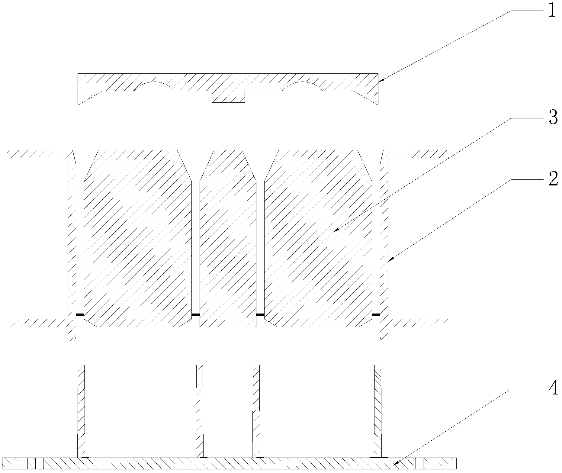
[0024] The technical solution of the present invention is a mold that uses a machine to make a composite cavity member, with figure 1 It is a schematic diagram of the mold structure in the technical solution of the present invention, as figure 1 As shown, the mold subsystem includes a top plate 1, an outer mold frame 2, an inner mold core 3, an opening pressure ring 4, and a mold core 15 for forming holes. The following is a detailed description and analysis of the various components of the mold subsystem in conjunction with the subsequent drawings:

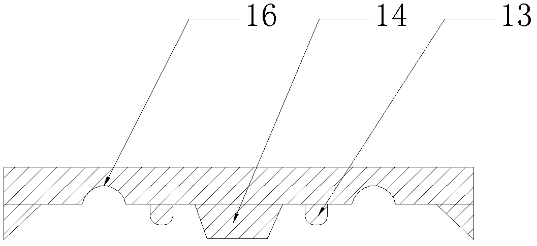
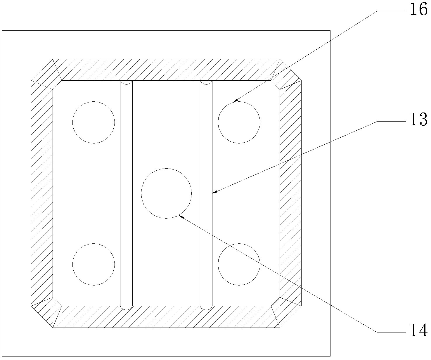
[0025] Fig. 2 is a schematic structural diagram of the top formwork, wherein Fig. 2(a) is a cross-sectional view of the top formwork 1, and Fig. 2(b) is a top view of the top formwork 1 turned upside down. As shown in Figure 2 (a), a hole-forming mold base 14 is provided on the inner surface of the top template 1, wherein...


PUM


Abstract

The invention relates to a die applied in a hydraulic mechanical system and used for pressing a combined cavity member. The die is a non-integrated die and consists of a top template, an outer die frame, an inner die core, a pore-forming die core and an open pressure head; and the die is easily assembled and disassembled by a unique connector fixed point connecting mode of the outer die frame, the inner die core and the pore-forming die core and through a unique opening of a corresponding connector part of the open pressure head. Assembly and disassembly of the whole die are controlled by a high-strength hydraulic machine, meanwhile, quick pressing formation of the cavity member is realized, and the cavity member is easily released from the die due to the split die design. After the technical scheme is adopted, mechanical production is realized by using an automatic control system, the production time of the cavity member is shortened, the production efficiency is improved, and the production and release time of the cavity member is shortened from 4 hours of manual production to about 1 minute; and the formed cavity member product is standard and has high density, high strength and attractive appearance.

Description

technical field [0001] The invention relates to a mold for making a concrete component by using a machine, in particular to a machine-made mold for making a combined cavity component in a cast-in-place cavity floor. Background technique [0002] At present, in the technical field of cast-in-place cavity floors, cavity floors are usually formed by casting cavity thin-walled box components, such as the ZL02282207.0 "thin-walled box embodied by the thin-walled box for pouring concrete hollow slabs" declared by the inventor. "Patent, the thin-walled box produced according to this patent has thin hollow walls, light weight and high strength. When it is applied to cavity floor projects, such as ZL200410082381.9 "an empty stomach and small ribbed floor" declared by the inventor, the hollow The cavity thin-walled box forms a hollow layer in the small dense ribbed floor, which can achieve the purposes of saving construction concrete, reducing the height of the building, improving the...

Claims


Application Information

Patent Timeline
Patent Type & Authority Patents(China)
IPC IPC(8): B28B7/22E04B5/36E04G15/06
Inventor 王本淼王海崴刘三幸
Owner HUNAN BDF ENERGY SAVING TECH
Why Eureka
Try Eureka