
Focusing system having grating structure

A concentrating system and grating structure technology, applied in the field of concentrating systems, to achieve effective diffraction coupling to collect light energy, save costs, and require small size

Active Publication Date: 2012-01-04
厦门市为纳光电科技有限公司
View PDF4 Cites 7 Cited by
  • Summary
  • Abstract
  • Description
  • Claims
  • Application Information

AI Technical Summary

Problems solved by technology

But the above patent is a one-dimensional structure, which only corresponds to one direction of polarization

Method used


Image

  • Focusing system having grating structure
  • Focusing system having grating structure
  • Focusing system having grating structure

Examples


Embodiment Construction

[0033] The present invention will be described in detail below with reference to the embodiments and accompanying drawings, but the protection scope of the present invention should not be limited by this.

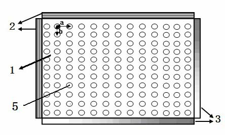
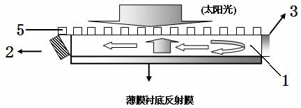
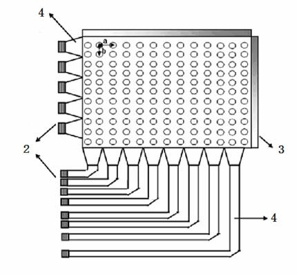
[0034] see first Figure 1-Figure 8 , as shown in the figure, a light concentrating system with a grating structure, including a two-dimensional grating 5 located on a thin film 1, a reflective film located on the substrate of the thin film 1, and the shape of the thin film 1 has three For the polygon with the above boundary, at least one boundary of the film 1 is connected with a backlight device, and the other boundary has a reflective film 3 .

[0035] figure 1 It is a top view of the first embodiment of the light concentrating system with grating structure according to the present invention, figure 2 It is a side view of the first embodiment of the light concentrating system with a grating structure of the present invention, that is, a light concentrating system comp...


PUM


Abstract

The invention relates to a focusing system having a grating structure. The system comprises a two-dimensional grating on a thin film; a shape of the thin film is a polygon having over three boundaries; at least one boundary of the thin film is connected with a backlight device and other boundaries have reflective films. According to the invention, a thickness of a film concentrator is further reduced; and solar energy is effectively utilized and is converted into a power source for indoor illumination, backlight of an LCD panel or a solar cell. Besides, with regard to illumination of solar energy, a requirement on chip size is low and a cost is saved.

Description

technical field [0001] The present invention relates to the technical field of light source acquisition in the field of illumination and display, in particular to a light concentrating system with a grating structure. Background technique [0002] In silicon-based optical communication, since the size of the waveguide used as optical interconnection is much smaller than that of the existing optical fiber, the traditional end-face alignment coupling, the input and output coupling efficiency of the optical signal is very low, and the alignment error requirements are very high. high. In order to improve the coupling efficiency and reduce the error requirement of the alignment, the mode matching between the input light and the waveguide using diffraction grating is proposed. For example, US Patent US005081615A discloses a one-dimensional grating to realize mutual conversion between spatial light and thin-film waveguide modes, while US Patent US5033812 discloses a structured wav...

Claims


Application Information

Patent Timeline
Patent Type & Authority Applications(China)
IPC IPC(8): G02B6/124G02B6/34H01L31/052H01L31/054
CPCY02E10/52
Inventor 叶志成郑纬芹
Owner 厦门市为纳光电科技有限公司
Learn More