

Pneumatic powder feeding type molten carbonate direct carbon fuel cell stack
A technology of molten carbonate and fuel cell stacks, applied in the direction of molten electrolyte fuel cells, fuel cell groups, fuel cell components, etc., to achieve the effects of easy implementation, improved overall performance, and enhanced heat and mass transfer process
- Summary
- Abstract
- Description
- Claims
- Application Information
AI Technical Summary
Problems solved by technology
Method used
Image


Examples
Embodiment 1
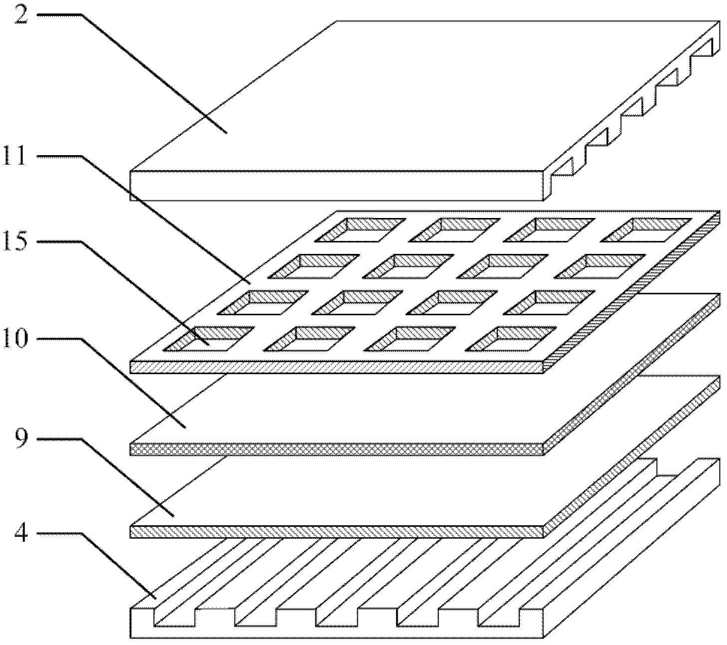
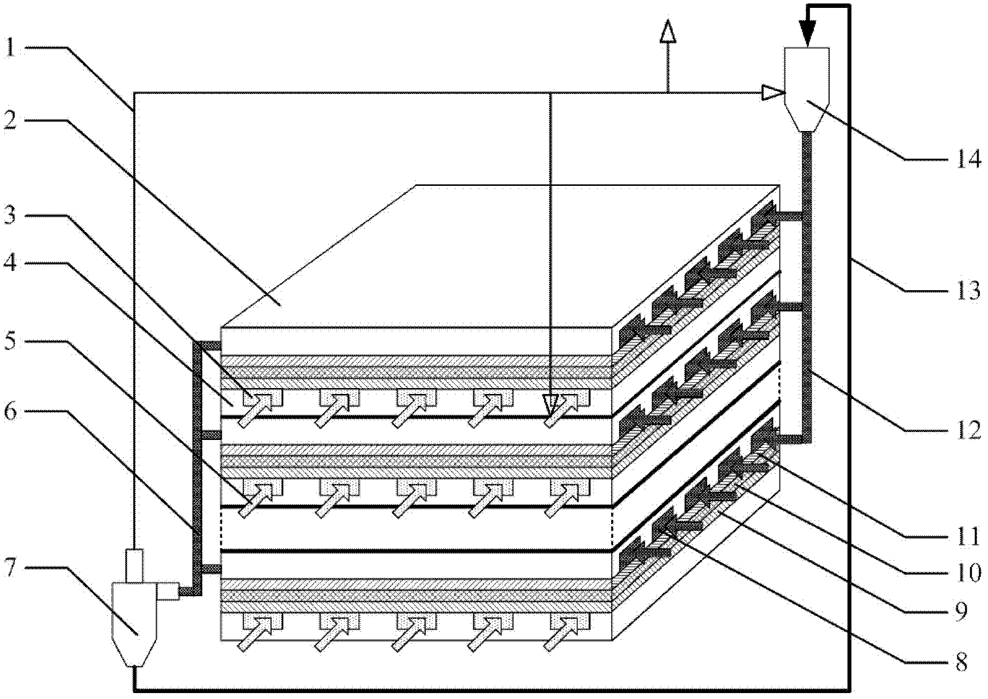
[0033] Such as figure 1 and figure 2 As shown, a gas powder-feeding type molten carbonate direct carbon fuel cell stack is formed by stacking 30 fuel cell monomers. Electrolyte diaphragm 10, cathode 9 and cathode current collecting plate 4 are compressed, anode current collecting plate 2 has multiple horizontal and parallel anode gas flow channels 8, and cathode current collecting plate 4 has multiple horizontal and parallel cathode gas flow channels The flow channel 3 and the anode 11 are evenly distributed with a plurality of anode plate openings 15, and each anode plate opening 15 communicates with one or more anode gas flow channels 8, and the entrance of the anode gas flow channel 8 communicates with the carbon fuel tank 14 The feed port of the anode gas flow channel 8 is connected to the air supply port of the cyclone separator 7, and there is CO 2 There is a carbon fuel circuit 13 between the gas circuit 1 , the ash discharge pipe of the cyclone separator 7 and the f...
Embodiment 2
[0039] The difference from Embodiment 1 is that the direction of the anode gas flow channel 8 and the cathode gas flow channel 3 are the same as each other, showing a downstream flow type; the number of fuel cell cells is 60, and the size of the cell cells is about 20cm×20cm; 43 %Li 2 CO 3 -57%K 2 CO 3 The mixture is used as the electrolyte; carbon black with a particle size of 2 mm to 100 μm is used as the solid carbon fuel; a 2:1 CO 2 Mixture with oxygen as cathode gas; pure CO 2 As the anode powder feeding gas, after the reaction, the outlet of the exhaust pipe of the cyclone separator is CO 2 50% enters the carbon fuel bin for gas transportation of carbon black powder, 40% enters the cathode gas flow channel, mixes with oxygen according to 2:1 and is used as cathode gas, and the remaining 10% is directly emptied; the working temperature of the battery stack is 700 ℃.
[0040] When the fuel cell stack is working, carbon black powder is stored in the carbon fuel bin 14...
Embodiment 3
[0043] The difference from Embodiment 1 is that the direction of the anode gas flow channel 8 and the cathode gas flow channel 3 are the same as each other, and they are in a countercurrent flow pattern; the number of fuel cell cells is 50, and the size of the cell cells is about 40cm×40cm; 43% Li 2 CO 3 -21%Na 2 CO 3 -36%K 2 CO 3 The mixture is used as electrolyte; coal with a particle size of 1mm-10nm is used as solid carbon fuel; 2:1 CO 2 Mixture with air as cathode gas; pure CO 2 As the anode powder feeding gas, after the reaction, the outlet of the exhaust pipe of the cyclone separator is CO 2 20% enters the carbon fuel bin for gas transportation of pulverized coal, 40% enters the cathode gas channel, mixes with air at a ratio of 2:1 and is used as cathode gas, and the remaining 40% is directly emptied; the working temperature of the battery stack is 750°C .
[0044] When the fuel cell stack is working, the pulverized coal is stored in the carbon fuel bin 14, and...
PUM
| Property | Measurement | Unit |
|---|---|---|
| Particle size | aaaaa | aaaaa |
Abstract
Description
Claims
Application Information