Solid oxide direct carbon fuel cell stack of tablet bubbling bed

A technology of solid oxide and fuel cell stacks, applied in the direction of solid electrolyte fuel cells, fuel cell groups, fuel cell components, etc., to solve the problem of continuous feeding, improve overall performance, and simple structure

Active Publication Date: 2011-08-31
HUANENG CLEAN ENERGY RES INST
View PDF3 Cites 10 Cited by
  • Summary
  • Abstract
  • Description
  • Claims
  • Application Information

AI Technical Summary

Problems solved by technology

[0007] The purpose of the present invention is to provide a direct carbon fuel cell that can solve the difficulty of using a flat single cell stack and the problem of continuous feeding of solid carbon fuel; strengthen the internal heat and mass transfer process of the battery stack, and improve the o

Method used


Image

  • Solid oxide direct carbon fuel cell stack of tablet bubbling bed
  • Solid oxide direct carbon fuel cell stack of tablet bubbling bed
  • Solid oxide direct carbon fuel cell stack of tablet bubbling bed

Examples


Embodiment 1

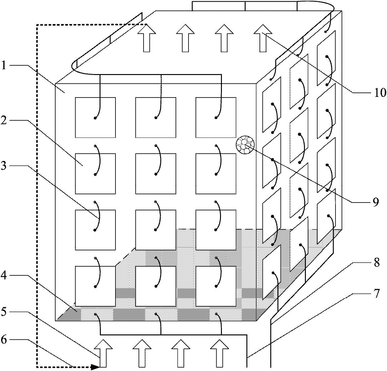
[0032] Example 1, see Figure 5 , this embodiment is composed of 48 anode-supported flat-plate fuel cell cells 2, and the size of the cell cell is about 10 cm × 10 cm; graphite with a particle size of 5 mm to 50 μm is used as the solid carbon fuel; the anode carrier gas component is pure CO 2 After the reaction, 70% of the anode carrier gas is exported for recycling; the working temperature of the battery stack is 800°C.

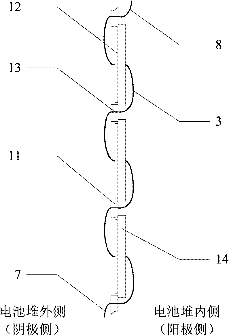
[0033] There are 3×4 (horizontal×vertical) rectangular holes of about 10cm×10cm on the walls around the bubbling bed, and the anode-supported flat-plate fuel cell cells 2 are respectively installed at the openings on the wall of the bubbling bed. The flat fuel cell unit 2 is composed of an anode 14 , an electrolyte 17 , and a cathode 12 in a three-layer structure. Among them, the anode 14 is the thickest and plays a supporting role to ensure the mechanical strength of the battery cell; the cathode 12 and the electrolyte 17 are relatively thin; the anode 14 ...

Embodiment 2

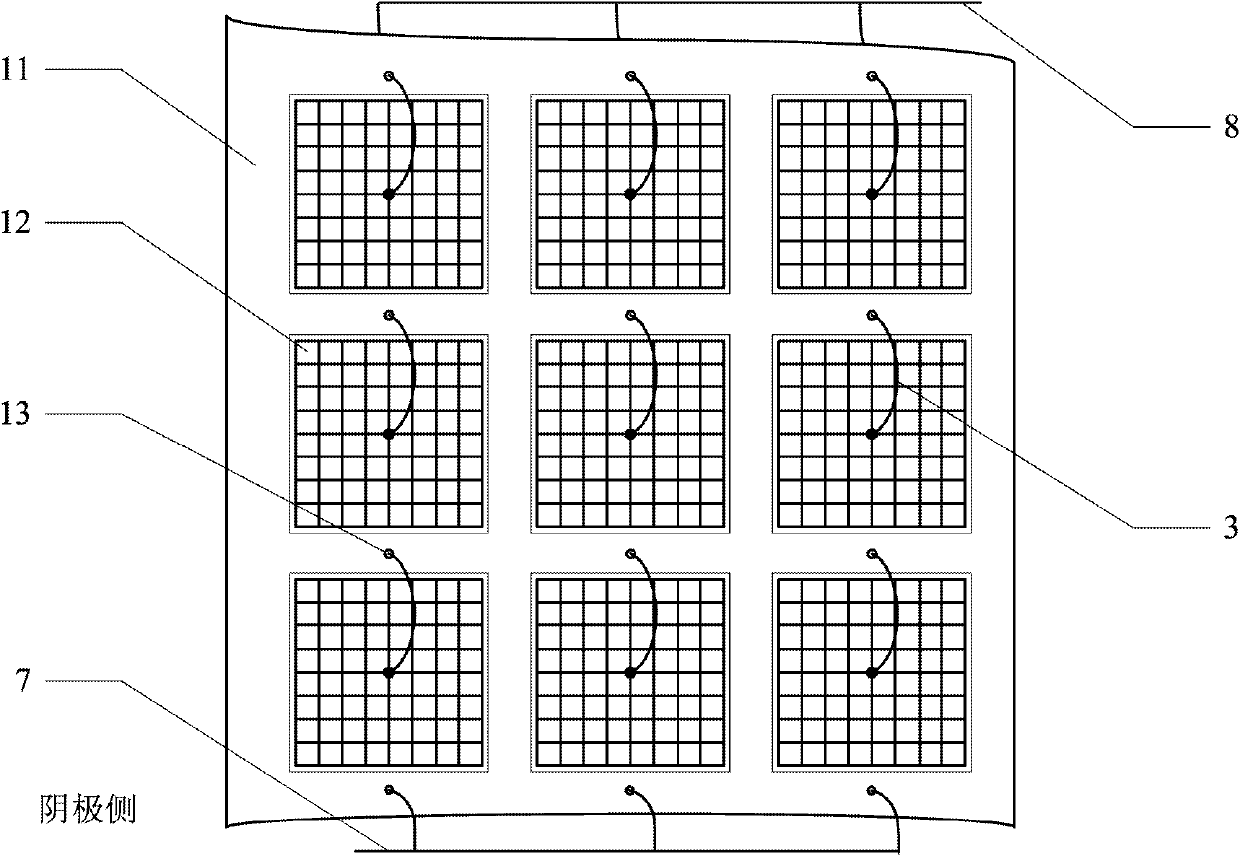
[0035] Example 2, see Figure 6 , this embodiment is composed of 64 electrolyte-supported flat-plate fuel cell cells 2, and the size of the cell cell is about 8cm×8cm; carbon black with a particle size of 5 mm to 100 μm is used as the solid carbon fuel; the anode carrier gas component is 70% CO 2 +30%H 2 O, 50% of the anode carrier gas exported after the reaction is used for recycling; the working temperature of the battery stack is 900°C.

[0036] There are 4×4 (horizontal×vertical) rectangular holes of about 8cm×8cm on the walls around the bubbling bed, and the electrolyte-supported flat-plate fuel cell cells 2 are respectively installed at the openings on the wall of the bubbling bed. Among them, the electrolyte 17 is the thickest and plays a supporting role, and the cathode 12 and the anode 14 are relatively thin; the electrolyte 17 has a larger area, while the area of ​​the cathode 12 and the anode 14 is slightly smaller than the electrolyte 17, and the electrolyte 17 i...

Embodiment 3

[0037] Example 3, see Figure 7 , this embodiment is composed of 100 cathode-supported flat-plate fuel cell cells 2, and the size of the cell cells is about 9cm×9cm; coal with a particle size of 5mm to 200μm is used as solid carbon fuel; the anode carrier gas component is 50% CO 2 +30%H 2 O+20%N 2 After the reaction, the outlet anode carrier gas is directly evacuated; the working temperature of the battery stack is 1000 °C.

[0038] There are 5×5 (horizontal×vertical) rectangular holes of about 9cm×9cm on the walls around the bubbling bed, and the cathode-supported flat-plate fuel cell cells 2 are respectively installed at the openings on the wall of the bubbling bed. Among them, the cathode 12 is the thickest and plays a supporting role, and the anode 14 and the electrolyte 17 are relatively thin; the cathode 12 and the electrolyte 17 have the same area, while the area of ​​the anode 14 is slightly smaller than the cathode 12 and the electrolyte 17, and the electrolyte 17 i...


PUM

PropertyMeasurementUnit
Particle sizeaaaaaaaaaa

Abstract

The invention relates to a solid oxide direct carbon fuel cell stack of a tablet bubbling bed, which belongs to the technical field of direct carbon fuel cells. The solid oxide direct carbon fuel cell stack provided by the invention comprises components such as a bubbling bed, tablet fuel cell monomers, a grid plate, a solid carbon fuel and the like, wherein the tablet fuel cell monomers are installed on the peripheral wall of the bubbling bed; an anode is inward and a cathode is outward; the tablet fuel cell monomers form a serial structure and a parallel structure through current collectingwires, thereby maintaining the working voltage and current which are needed by the cell stack; the grid plate is installed at the bottom of the bubbling bed; the solid carbon fuel is laid on the gridplate; inlet anode carrier gas is blown into the bubbling bed through the grid plate so as to blow solid carbon fuel particles, thereby enabling the solid carbon fuel particles to be in a bubbling fluidized state; and the cell stack can adopt anode support, electrolyte support or cathode support type tablet fuel cell monomers, and the working temperature of the cell stack is 600-1000 DEG C. The solid oxide direct carbon fuel cell stack provided by the invention has the advantages of compact and reasonable structure, low equipment requirements and easiness in realization, can be used for solving the difficulty of a tablet cell monomer stack and simultaneously realizing the continuous feeding of the solid carbon fuel.

Description

technical field [0001] The invention belongs to the technical field of direct carbon fuel cells, in particular to a flat-type bubbling bed solid oxide direct carbon fuel cell stack. Background technique [0002] Energy is the pillar of the national economy and the driving force necessary for the development of human society. my country is one of the few countries in the world that uses coal as the main energy source, accounting for more than 70% of the total primary energy, and for a long period of time in the future, it is difficult to change the status quo of my country's coal-based energy. Compared with developed countries, the utilization efficiency of coal-fired power generation in my country is relatively low, and the situation of energy waste and environmental pollution is serious. Therefore, it is imperative to explore clean and efficient coal utilization methods. [0003] At present, fuel cell is one of the research hotspots of clean energy technology in the world...

Claims


Application Information

Patent Timeline
IPC IPC(8): H01M8/24H01M8/10H01M8/02H01M2/26
CPCY02E60/12Y02E60/521Y02E60/50
Inventor 许世森李晨程健徐越王保民
Owner HUANENG CLEAN ENERGY RES INST
Why Eureka
Try Eureka