Leakage detecting protection circuit capable of periodically automatically detecting function integrity

A leakage detection and protection circuit technology, which is applied in the direction of automatically disconnected emergency protection devices, emergency protection circuit devices, and measuring power, can solve the problems of not being able to automatically detect whether the leakage protection function is intact, and achieve low cost, convenient use, and responsive effect

Active Publication Date: 2012-01-04
黄华道
View PDF5 Cites 48 Cited by
  • Summary
  • Abstract
  • Description
  • Claims
  • Application Information

AI Technical Summary

Problems solved by technology

[0002] With the continuous development of the power socket with leakage protection function (referred to as GFCI), power plug and power switch industry, people have higher and higher requirements for the function and safety of power socket with leakage protection function and power plug, so this Such products need to be equipped with a corresponding leakage detection protection circuit. When a leakage current occurs during use, it is necessary to trip in time and disconnect the power supply in time. In addition, a manual test function must be set, that is, a simulated leakage current is generated by human operation to make it trip, such as the application number A leakage detection and protection circuit was publishe

Method used


Image

  • Leakage detecting protection circuit capable of periodically automatically detecting function integrity
  • Leakage detecting protection circuit capable of periodically automatically detecting function integrity
  • Leakage detecting protection circuit capable of periodically automatically detecting function integrity

Examples


Embodiment 1

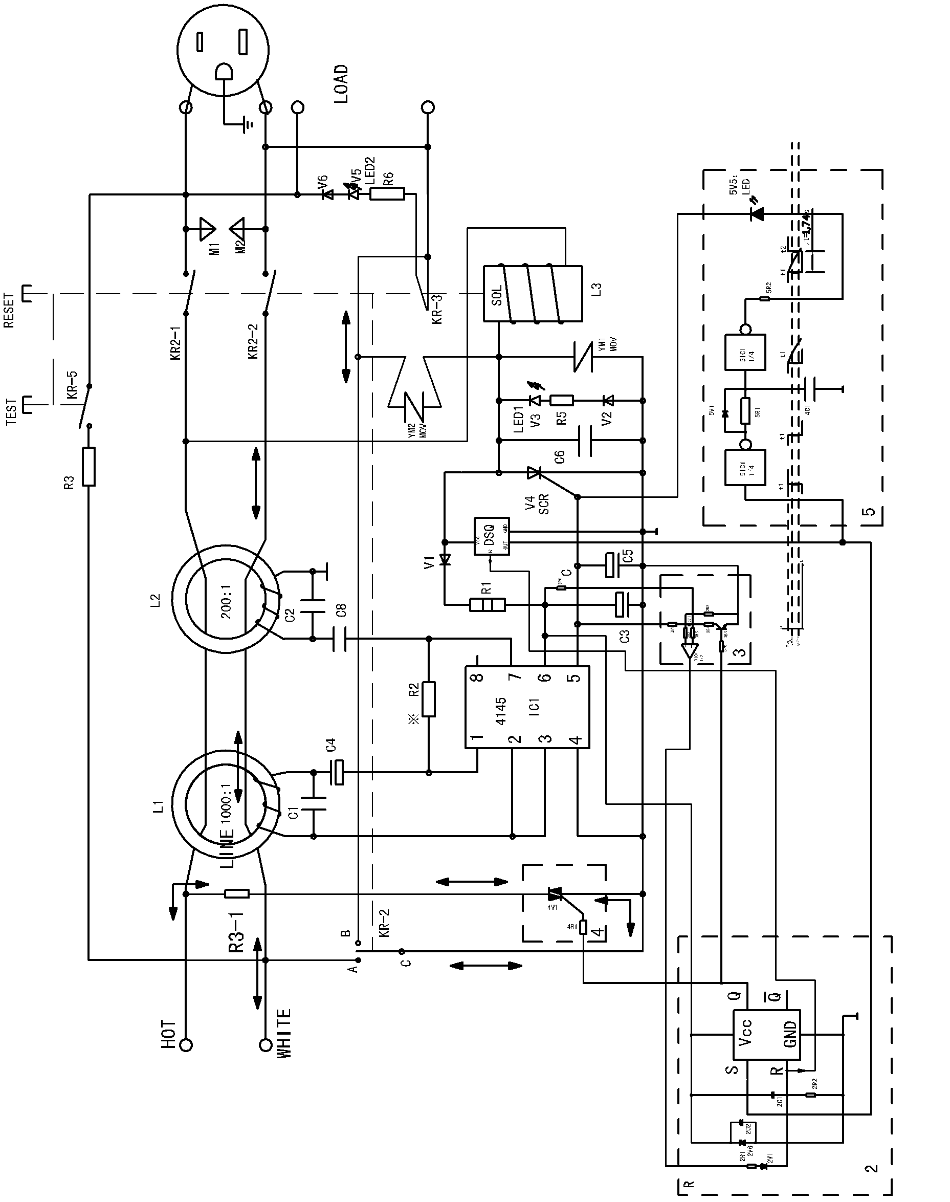
[0047]refer to figure 1 and figure 2 , Leakage detection protection circuit that can automatically detect functional integrity at regular intervals, including main circuit switches KR2-1, KR2-2, reset button RESET, tripping coil L3 that can cooperate with the mechanical structure to disconnect the main circuit switch, and control tripping coil The thyristor V4 for switching on and off the power supply circuit, the induction coil L1 for detecting leakage current, the self-induction coil L2 for detecting low-resistance faults, and the control chip IC1 for driving the thyristor on and off through the detection result of leakage current, also includes a) Timer DSQ for regularly outputting the functional integrity detection signal; b) Detection signal latch circuit 2; c) Analog test switch 4 for generating simulated leakage current; d) Delayed output circuit 5; e) Used for intercepting The sampling circuit 3 that controls the output current of the chip; the timer outputs the dete...

Embodiment 2

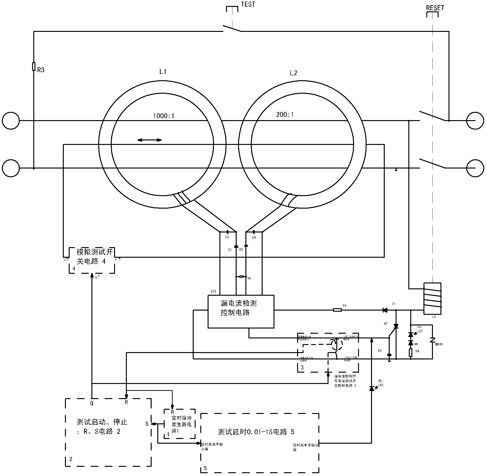
[0060] refer to Figure 19 , the leakage detection and protection circuit of this embodiment is also provided with a SPDT analog power supply switch KR-2 linked with the reset button, but its structure is different, its first static contact terminal A is connected to one of the power supply input terminals, Its second static contact terminal B is connected to the corresponding power supply output terminal, and its moving contact rod C is connected to another power supply input terminal passing through the end of the self-induction coil L2 for detecting low-resistance faults; when the reset button is in the tripping state , the moving contact rod C of the analog power supply switch KR-2 is connected to the second static contact terminal B, and the analog power supply switch KR-2 is in a closed state; when the reset button is pressed, the moving contact rod C of the analog power supply switch KR-2 Disconnect from the second static contact terminal B, and automatically disconnect...

Embodiment 3

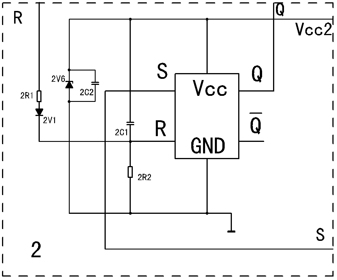
[0065] refer to Figure 20 , the latch circuit 2 of this embodiment is composed of an RS flip-flop integrated chip and peripheral circuits; the sampling circuit 3 is composed of a comparator and an electronic switch 3V3, and the triode used in the electronic switch here (if the required drive current is small, it can also be used FET); the triac V4 used in the analog detection switch 4; the combination of an inverter and a discharge circuit used in the delay output circuit 5.

[0066] The moving contact rod C of the analog power supply switch KR-2 in this embodiment is connected to the neutral line at the rear end of the main circuit neutral switch KR2-2 through the tripping coil L3 and the piezoresistor YM2 (that is, the neutral line at the output terminal), and the static contact terminal B is connected to the HOT terminal of the power input live wire, and the static contact terminal A is connected to the HOT tap of the live wire passing through the self-excited coil L2. The...


PUM


Abstract

The invention provides a leakage detecting protection circuit capable of periodically automatically detecting function integrity. The leakage detecting protection circuit comprises a main loop switch, a resetting button, a tripping coil, a silicon controlled rectifier, an induction coil for detecting leakage current, a self-induction coil for detecting a low-resistance failure and a control chip which drives the switching-on/off of the silicon controlled rectifier by a leakage current detection result, and further comprises a) a timer for periodically outputting a function integrity detection signal, b) a detection signal latching circuit, c) an analogue test switch for generating analogue leakage current, d) a delay output circuit and e) a sampling circuit, wherein the timer outputs the detection signal to the latching circuit and the delay output circuit; and if a function is detected to fail, the delay output circuit outputs a tripping signal to switch the silicon controlled rectifier on, and the main loop switch is switched off. The leakage detecting protection circuit has the main advantages of periodically automatically detecting whether the leakage protection function of the circuit is integral or not without annual testing and avoiding tripping within the service life of the circuit, along with more convenience of use.

Description

technical field [0001] The invention relates to a leakage detection and protection circuit applied to electric appliances such as power sockets with leakage protection function, and in particular to a leakage detection and protection circuit that can automatically detect the functional integrity at regular intervals. If the leakage protection function is intact, the detection process will not trip. If the function is damaged, it will trip automatically. Background technique [0002] With the continuous development of the power socket with leakage protection function (referred to as GFCI), power plug and power switch industry, people have higher and higher requirements for the function and safety of power socket with leakage protection function and power plug, so this Such products need to be equipped with a corresponding leakage detection protection circuit. When a leakage current occurs during use, it is necessary to trip in time and disconnect the power supply in time. In ...

Claims


Application Information

Patent Timeline
IPC IPC(8): H02H3/32G01R31/02
Inventor 黄华道陆华洋
Owner 黄华道
Why Eureka
Try Eureka