
High temperature, high efficiency thermoelectric module

A thermoelectric module and high-temperature technology, which is applied in thermoelectric device parts, manufacturing/processing of thermoelectric devices, thermoelectric device junction lead-out materials, etc., can solve problems such as degradation performance and cross-contamination

Inactive Publication Date: 2012-01-04
HI Z TECH
View PDF7 Cites 13 Cited by
  • Summary
  • Abstract
  • Description
  • Claims
  • Application Information

AI Technical Summary

Problems solved by technology

However, the manufacturing cost of this prior art module greatly exceeds the manufacturing cost of the bismuth telluride module described above
Also, after about 1000 hours of operation, some evaporation from the hot side P and N pins can lead to cross-contamination of all pins, resulting in degraded performance

Method used


Image

  • High temperature, high efficiency thermoelectric module
  • High temperature, high efficiency thermoelectric module
  • High temperature, high efficiency thermoelectric module

Examples


Embodiment Construction

[0064] first preferred embodiment

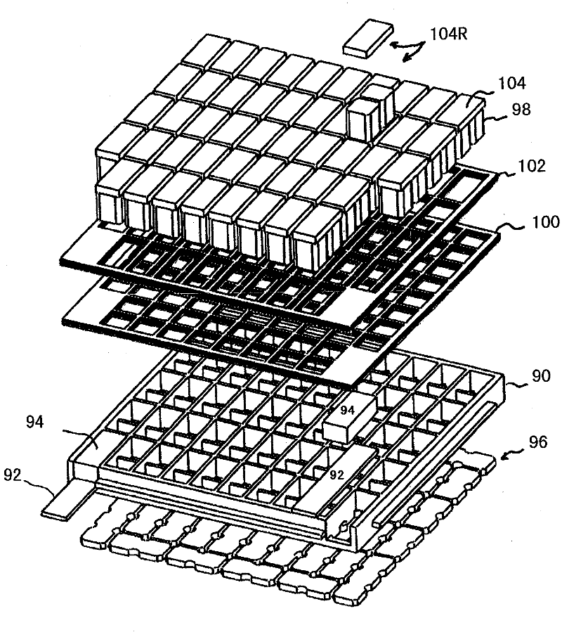
[0065] The first preferred embodiment of the present invention can be seen by referring to the attached Figure 4 , 4A and 7 to describe. Figure 4 and 4A From parent application S / N.12 / 317,170, but this first preferred module is a substantially improved and more efficient version of the embodiment described in the parent application, which is hereby incorporated by reference. For example, a significant difference is that the first preferred embodiment of the present application uses three segmented thermoelectric legs in the module instead of only two segments. Specifically, for this preferred embodiment, Figure 4 and Figure 4A Each of the segments 72a and 74a shown in is composed of two types of lead telluride material instead of only one type as in the parent application. exist Figure 7 This preferred embodiment is shown in more detail in , where the two types of lead telluride material in each pin are cl...


PUM

PropertyMeasurementUnit
melting pointaaaaaaaaaa

Abstract

A long life, low cost, high-temperature, high efficiency thermoelectric module. Preferred embodiments include a two-part (a high temperature part and a cold temperature part) egg-crate and segmented N legs and P legs, with the thermoelectric materials in the three segments chosen for their chemical compatibility or their figure of merit in the various temperature ranges between the hot side and the cold side of the module. The legs include metal meshes partially embedded in thermoelectric segments to help maintain electrical contacts notwithstanding substantial temperature variations. In preferred embodiments a two-part molded egg-crate holds in place and provides insulation and electrical connections for the thermoelectric N legs and P legs. The high temperature part of the egg-crate is comprised of a ceramic material capable of operation at temperatures in excess of 5000C and the cold temperature part is comprised of a thermoplastic material having very low thermal conductivity.

Description

technical field [0001] The invention relates to a thermoelectric module, in particular to a high-temperature thermoelectric module. [0002] Cross References to Related Applications [0003] This application is a continuation-in-part of S / N.12 / 317,170 filed December 19,2008. Background of the invention [0004] thermoelectric material [0005] The Seebeck coefficient of a thermoelectric material is defined as the open circuit voltage developed between two points on a conductor between which there is a uniform 1K temperature difference. [0006] The figure of merit of a thermoelectric material is defined as: Z = α 2 σ λ [0007] where α is the Seebeck coefficient of the material, σ is the electrical conductivity of the material, and λ is the overall thermal conductivity of the material. [0008] Many semiconductor mater...

Claims


Application Information

Patent Timeline
Patent Type & Authority Applications(China)
IPC IPC(8): H01L35/12
CPCH01L35/32H01L35/16H01L35/34H10N10/852H10N10/01H10N10/17H10N10/80
Inventor F·A·莱维特N·B·埃尔斯纳J·C·巴斯J·W·麦考伊
Owner HI Z TECH
Learn More