Production process for a microneedle arrangement and corresponding microneedle arrangement and use

A manufacturing method and technology of microneedles, applied in the direction of microstructure devices, manufacturing microstructure devices, microelectronic microstructure devices, etc., can solve the problems of cost increase and achieve the effect of improving output

Inactive Publication Date: 2012-01-11
ROBERT BOSCH GMBH
View PDF8 Cites 2 Cited by
  • Summary
  • Abstract
  • Description
  • Claims
  • Application Information

AI Technical Summary

Problems solved by technology

If a large area is sacrificed for this, the cost increases rapidly, because this cost increases linearly with the wafer area

Method used


Image

  • Production process for a microneedle arrangement and corresponding microneedle arrangement and use
  • Production process for a microneedle arrangement and corresponding microneedle arrangement and use
  • Production process for a microneedle arrangement and corresponding microneedle arrangement and use

Examples


Embodiment Construction

[0032] In the figures, identical reference numbers designate identical or functionally identical components.

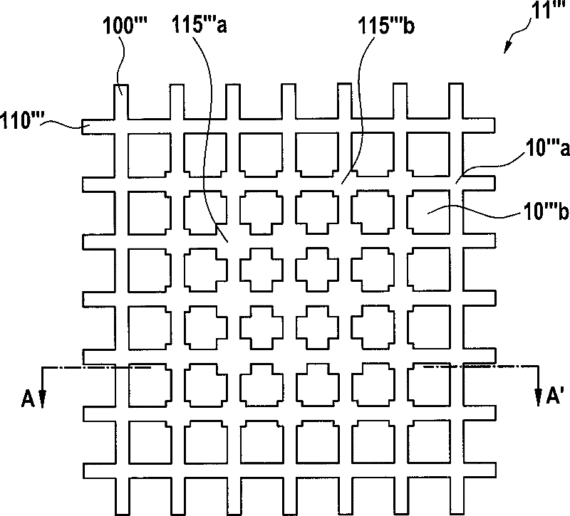
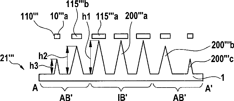
[0033] Figure 1a , b are schematic diagrams for explaining the first embodiment of the manufacturing method of the microneedle device according to the present invention, specifically, Figure 1a For the top view of the etched grid, Figure 1b for the etched grid and the resulting microneedle device along the Figure 1a A cross-sectional view of line A-A'.

[0034] The reference numeral 10' designates an etching mask in the first embodiment. This etch mask is as Figure 8a The etch mask 10 of , b has a regular orthogonal grid composed of horizontal grid tabs 100' and vertical grid supports 110'. The grid intersection areas are indicated with reference numeral 10'a and the grid openings with reference numeral 10'b.

[0035] In contrast to the above-described etch mask 10, this etch mask 10' has a square reinforcement area 115' in the grid intersection area 10'a. ...


PUM


Abstract

A production process for a microneedle arrangement and a corresponding microneedle arrangement as well as a use for it is disclosed. The process has the following steps: forming an etching mask (10'; 10''; 10''') in grid form, with grid bars (100', 110'; 100'', 110''; 100''', 110''') with corresponding grid crossing regions (10'a; 10''a; 10'''a) and grid openings (10'b; 10''b; 10'''b) in between on a substrate (1); carrying out an etching process to form the microneedle arrangement (20'; 20''; 20'''; 21'''; 22''') on the substrate (1) using the etching mask (10'; 10''; 10'''; 11'''; 12'''; 13'''; 14'''); and removing the etching mask (10'; 10''; 10'''; 11'''; 12'''; 13'''; 14'''). The etching mask (10'; 10''; 10''') in grid form has at least some of the grid crossing regions (10'a; 10''a; 10'''a) flat reinforcing regions (115'; 115''a; 115''b), which extend beyond the grid bars (100', 110'; 100'', 110''; 100''', 110''').

Description

technical field [0001] The invention relates to a manufacturing method of a microneedle device, a corresponding microneedle device and applications. Background technique [0002] Although applicable to any micromechanical components, the invention and the background on which it is based are described in silicon technology with respect to micromechanical components. [0003] Microneedle devices—which, for example, have microneedles made of porous silicon—are used in the field of "Transdermal Drug delivery" as an extension of ointments, carriers for vaccines, or also for extracting body fluids (so-called Intermediate Interstitial Fluid—Transdermal fluid) for diagnosis and analysis of body parameters (eg glucose, lactate). [0004] Transdermal patches for small molecules such as nicotine have been published in detail. To expand the field of use of such skin-penetrating active substances, so-called chemical intensifiers, or different physical methods (ultrasound, heat pulses),...

Claims


Application Information

Patent Timeline
Patent Type & Authority Applications(China)
IPC IPC(8): B81C1/00B81B1/00B81B7/04A61B17/20A61M37/00
CPCB81B2203/0361A61M2037/0053B81B2201/055A01K11/005A61M2037/0046B81C1/00111B81C2201/0132A61M37/0015A61M2037/0061A61M37/0076
Inventor M.施通贝尔F.沙茨
Owner ROBERT BOSCH GMBH
Why Eureka
Try Eureka