Turbo-charging apparatus for vehicle engine

A turbocharging device, turbocharger technology, applied in the direction of engine components, combustion engines, machines/engines, etc., can solve the problems of reduced supercharging efficiency, longer channel length, slow catalyst activation, etc., and achieves a simple structure Effect

Active Publication Date: 2012-01-11
MAZDA MOTOR CORP
View PDF8 Cites 11 Cited by
  • Summary
  • Abstract
  • Description
  • Claims
  • Application Information

AI Technical Summary

Problems solved by technology

However, since the inter-turbine passage for connecting the discharge portion of the small turbocharger turbine to the inlet portion of the large supercharger turbine is arranged above the small turbocharger turbine by bypassing the small turbocharger turbine, The passage between the turbines is basically formed in a U-shape, and there is a possibility that the passage length may become longer
In this way, when the passage between the turbines is long, the heat energy of the exhaust gas will be released to the outside air, and problems such as a decrease in supercharging efficiency due to a decrease in exhaust kinetic energy, a decrease in DPF regeneration efficiency, and a delay in catalyst activation are worrisome.

Method used


Image

  • Turbo-charging apparatus for vehicle engine
  • Turbo-charging apparatus for vehicle engine
  • Turbo-charging apparatus for vehicle engine

Examples


Embodiment 1

[0045] Below, based on Figure 1 to Figure 18 Example 1 of the present invention will be described.

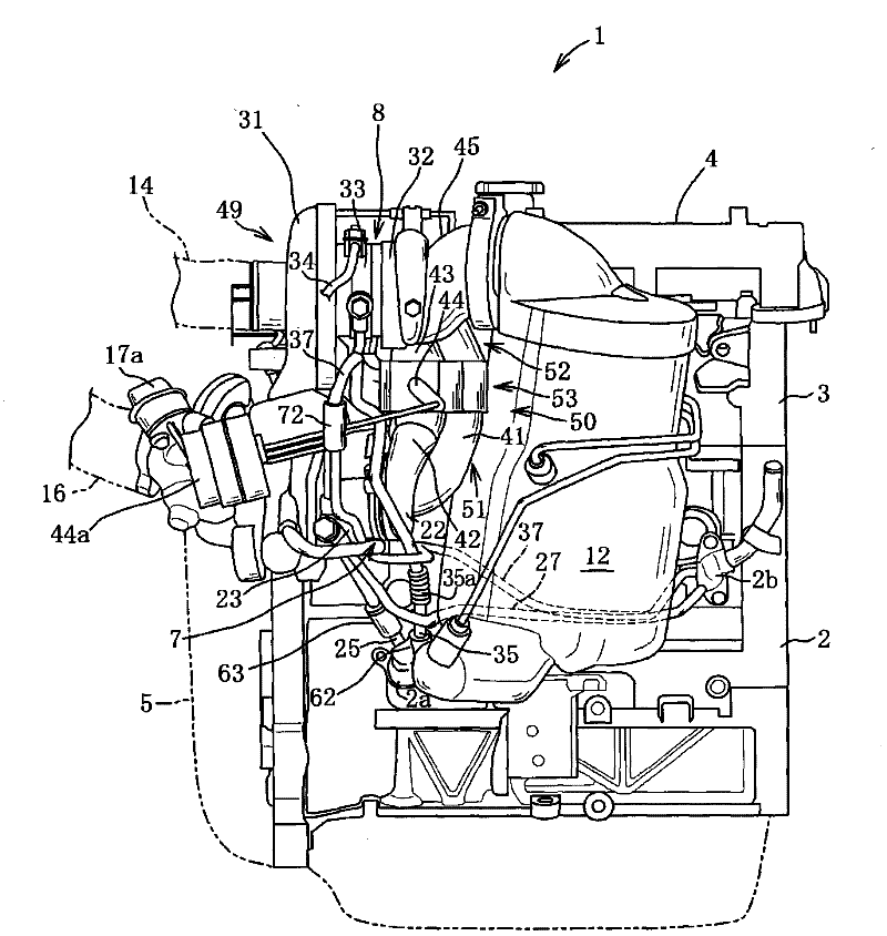
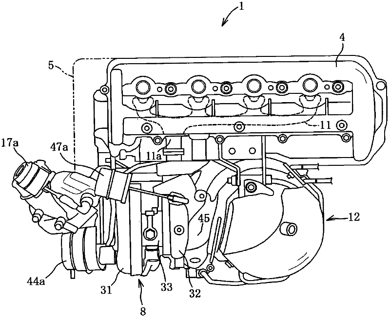
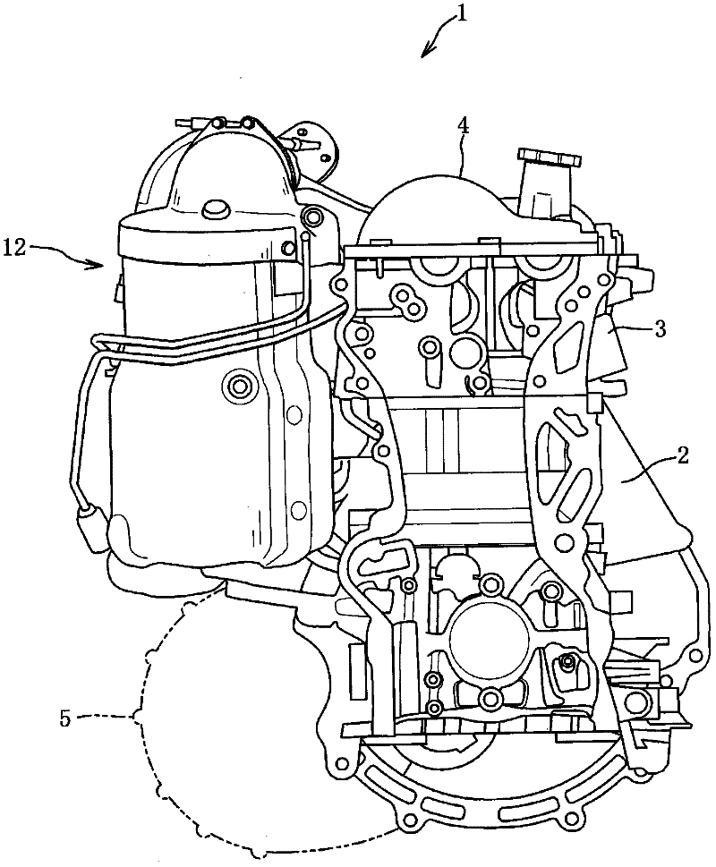
[0046] Such as Figure 1 ~ Figure 3 As shown, an in-line 4-cylinder diesel engine 1 has a cylinder block 2, a cylinder head 3 disposed on the upper portion of the cylinder block 2, a cylinder head 4 covering the upper portion of the cylinder head 3, and a cylinder head 4 disposed on the left end of the cylinder block 2. Department of the transmission unit 5 and so on.

[0047] The engine 1 is arranged horizontally so that the direction of the crankshaft (not shown) is the direction of the vehicle axis, and the intake port 3a is located on the vehicle front side, and the exhaust port 3b is located on the vehicle rear side. The engine 1 is configured such that the compression ratio in the compression stroke is controlled to be lower than that of a normal diesel engine, for example, the compression ratio is about 14. The transmission unit 5 has a transfer case (not shown) coveri...


PUM


Abstract

The disclosure provides a turbo-charging apparatus for a vehicle engine, which includes a first and second turbocharger, an inter-turbine passage connecting a discharging port of a first turbocharger turbine with an introducing port of a second turbocharger turbine, a bypass passage connecting an introducing passage of the first turbocharger turbine with the inter-turbine passage, and a control valve for opening and closing the bypass passage. The inter-turbine passage extends substantially straight from the discharging port of the first turbocharger turbine toward the second turbocharger when viewed from a direction parallel to turbine shafts of the first and second turbochargers, which are arranged substantially parallel to each other, so that the inter-turbine passage connects with an outer circumferential part of the second turbocharger turbine so as to extend in a direction tangent to an outer circumference direction of the second turbocharger turbine.

Description

technical field [0001] The present invention relates to a turbocharger for a vehicle engine, and more particularly to a turbocharger for a vehicle engine including a first turbocharger and a second turbocharger arranged in series with the first turbocharger. Background technique [0002] In the past, it is known that in a diesel engine, by reducing the compression ratio of the compression stroke, the mechanical resistance of each bearing portion can be reduced to achieve the purpose of improving fuel economy. In addition, due to the reduction of the compression ratio, the combustion temperature can be reduced and thus Reduce NO contained in exhaust gas x . However, reducing the compression ratio as described above leads to a reduction in engine output. Therefore, as an effective means for reducing the compression ratio and reducing the output power of the engine, a turbocharger that uses the kinetic energy of the exhaust gas discharged from the engine to supercharge the in...

Claims


Application Information

Patent Timeline
Patent Type & Authority Applications(China)
IPC IPC(8): F02B37/013
CPCF02B29/0406F02B37/127F02M25/0713F02M25/0728F02B37/013F02M25/0711Y02T10/144F02B39/00F02B37/004F02B37/183F02M26/08F02M26/10F02M26/25F02B37/162Y02T10/12
Inventor 丹羽靖末国荣之介旗生笃宏西坂聪
Owner MAZDA MOTOR CORP
Why Eureka
Try Eureka