Sinter grading charging method

A technology of sintering ore and sintering materials, which is applied in the field of blast furnace smelting, can solve the problems of not being able to effectively improve the air permeability of large-scale blast furnace material columns, not being able to adjust the reasonable distribution of gas flow, and being unfavorable for the stable and smooth flow of blast furnaces, etc., so as to improve the utilization rate of gas, Flexible adjustment, control effect of particle size segregation

Inactive Publication Date: 2012-01-18
武钢集团有限公司
View PDF2 Cites 11 Cited by
  • Summary
  • Abstract
  • Description
  • Claims
  • Application Information

AI Technical Summary

Problems solved by technology

However, this method not only increases the workload of classification, but also for large-scale blast furnaces, when sintering into the furnace, the block belt height and resistance are much larger than those of small blast furnaces, and the position of the lower reflow zone is generally used to expand the indirect reduction zone. The area of ​​the shaped belt is relatively enlarged, and the resistance of the gas flow is relatively large. If the sintered material is only graded into the furnace, and the proportion, dosage and drop point of the sintered ore at all levels are ignored, the air permeability of the large-scale blast furnace material column cannot be effectively improved, and the reduction The resistance of the small gas flow makes it impossible to adjust the reasonable distribution of the gas flow, resulting in large fluctuations in the furnace condition, which is not conducive to the smooth running of the blast furnace and reduces the life of the blast furnace

Method used


Image

  • Sinter grading charging method
  • Sinter grading charging method
  • Sinter grading charging method

Examples


Embodiment Construction

[0014] The present invention will be further described in detail below in conjunction with the accompanying drawings and specific embodiments.

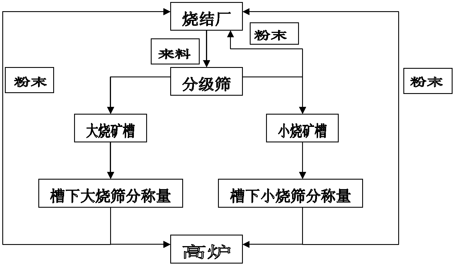
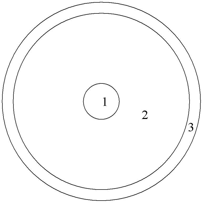
[0015] The sintering method shown in the figure is to classify the incoming materials from the sintering plant through the grading sieve according to the particle size D. The particle size of the primary sintering material is D≥13mm, and the particle size of the secondary sintering material is 4≤D<13mm. , put into the corresponding ore trough after classification, weigh under the ore trough and send it into the blast furnace. The radial periphery of the first-grade sintering material, its proportion is 20% to 25% of the total ore mix in the blast furnace, and the occupied width is 1 / 30 to 1 / 18 of the inner diameter of the furnace, and the particle size D<4mm sintering material is returned as powder To the sintering plant for re-sintering.

[0016] Embodiment: A screening building is set up between the sintering ore transport belt and...


PUM

PropertyMeasurementUnit
particle diameteraaaaaaaaaa

Abstract

The invention discloses a sinter grading charging method, which comprises the following steps: dividing incoming materials from sintering plants into at least two grades of sintering materials by a grading sieve according to the particle size D; allowing the graded sintering materials to enter respectively into corresponding ore grooves, delivering the graded sintering materials into a blast furnace through the ore grooves, wherein the particle size of primary sintering materials is larger than the particle size of secondary sintering materials; radially distributing the primary sintering materials and the secondary sintering materials entering the blast furnace in the hearth; allowing the secondary sintering materials to be distributed at the radial periphery of the primary sintering materials. The invention effectively controls the particle size segregation during the charging process, improves the permeability of the material layer, reasonably controls the distribution of coal gas, allows the adjustment of furnace top material distribution to be more flexible, facilitates the realization of large batch, alleviates the contradiction of sinter supply shortage and large particle size fluctuation, greatly increases the utilization rate of coal gas, increases the yield, reduces the coke rate and fuel consumption, and creates favorable conditions for the stable operation of blast furnaces.

Description

technical field [0001] The invention relates to the technical field of blast furnace smelting, in particular to a method for grading sintered ore into a large blast furnace. Background technique [0002] During blast furnace smelting, the entire block-shaped material column in the furnace is a bed of bulk material, and the gas flows zigzagging between the gaps of the accumulated bulk material particles. The better the performance, the more favorable it is for the smooth operation of the blast furnace, which lays the foundation for improving the utilization rate of gas and making full use of resources. The gas flow in the blast furnace mainly has three distributions: the initial air flow distribution in the tuyere swirl area of ​​the blast furnace, the secondary air flow distribution in the reflow zone, and the tertiary air flow distribution in the bulk material column. The porosity of the bulk material bed is an important factor affecting the gas flow distribution, and the ...

Claims


Application Information

Patent Timeline
Patent Type & Authority Applications(China)
IPC IPC(8): C22B1/16
Inventor 尹腾陆隆文
Owner 武钢集团有限公司
Why Eureka
Try Eureka