
Electrode introduction device

A technology for introducing devices and electrodes, applied in gaseous chemical plating, metal material coating process, coating and other directions, can solve the problems of stainless steel shovel affecting electrode contact stability, complex structure, heavy metal shovel, etc.

Active Publication Date: 2012-01-18
北京硅元科电微电子技术有限责任公司
View PDF3 Cites 12 Cited by
  • Summary
  • Abstract
  • Description
  • Claims
  • Application Information

AI Technical Summary

Problems solved by technology

This electrode connection method is only suitable for manual boat release, not for automatic boat retrieval by manipulators, and cannot meet the requirements of large-scale production
[0004] Moreover, in the four-tube horizontal PECVD, the cantilever furnace door is the feeding and discharging device of the equipment, and is one of the most important structures to ensure the process. The traditionally used cantilever furnace door structure is a double-rod shovel mechanism, and the graphite boat falls on the On the metal shovel, the metal shovel enters the reaction chamber together with the graphite boat for film deposition. Due to the high temperature of the deposition process, the stainless steel shovel is heated in the reaction chamber for a long time and is easily deformed. Moreover, the metal shovel is relatively heavy and has a complicated structure. Processing Difficulty, the deformation of the stainless steel shovel directly affects the stability of the electrode contact introduced inside the equipment

Method used


Image

  • Electrode introduction device
  • Electrode introduction device
  • Electrode introduction device

Examples


Embodiment Construction

[0023] The specific implementation manners of the present invention will be further described in detail below in conjunction with the accompanying drawings and embodiments. The following examples are used to illustrate the present invention, but are not intended to limit the scope of the present invention.

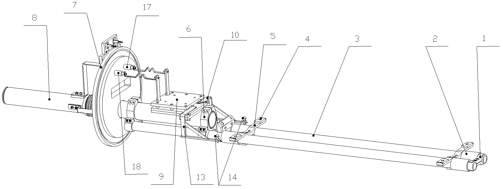
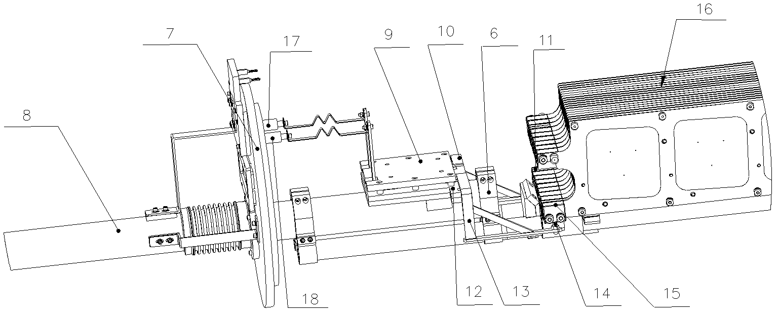
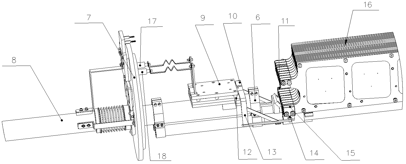
[0024] figure 1 A schematic structural view of a cantilever furnace door supporting a graphite boat according to an embodiment of the present invention is shown, figure 2 A schematic structural view of the electrode introducing device according to the embodiment of the present invention is shown.

[0025] refer to figure 2 , the electrode introduction device is connected with the furnace door electrode and the electrode block of the graphite boat 16, and charges are introduced into the graphite boat 16 from the furnace door 7 position. The electrode introduction device specifically includes a first electrode support 10 and a second electrode support 13, one end of the...


PUM


Abstract

The invention relates to plasma enhanced chemical vapor deposition equipment, and discloses an electrode introduction device, which comprises two parallel electrodes brackets, wherein one end of each electrode bracket is connected with a furnace door electrode, and the other end of the electrode bracket is a metal contact and is connected with an electrode block on a graphite boat. The electrode introduction device also comprises a connecting rod penetrating through a furnace door, wherein one end of the connecting rod extending into the inner side of the furnace door is connected with a graphite boat supporting rod, and the graphite boat supporting rod is at least two parallel silicon carbide rods. In the invention, the electrode introduction device adopts a lapped joint mode, the metal contacts are directly connected with the furnace door electrodes through the graphite boat supporting rods, two graphite pads on the graphite boat act as the two electrode blocks, and a bulge is arranged on each metal contact at the position contacted with a groove on the electrode block, accordingly, the contact is good, and the degree of automation is high; the silicon carbide dual rods can withstand the temperature of over 1000 DEG C and are not easily deformed, so the stability of electrode contact is improved; and a mechanical mechanism is simple, the cost is low, and the assembly difficulty is reduced.

Description

technical field [0001] The invention relates to plasma enhanced chemical vapor deposition equipment, in particular to an electrode introduction device. Background technique [0002] The function of the four-tube horizontal plasma-enhanced chemical vapor deposition (Plasma Enhanced Chemical Vapor Deposition, PECVD) equipment is to use high-frequency electric field excitation in the high-vacuum quartz chamber to decompose the process gas SiH 4 , NH 3 , the deposition on the sample surface forms Si 3 N 4 film. deposited Si 3 N 4 When, not only grow Si 3 N 4 As an anti-reflection film, a large number of hydrogen atoms are generated at the same time. These hydrogen atoms not only have a surface passivation effect, but also can passivate dislocations and surface dangling bonds in silicon, thereby improving carrier mobility in silicon wafers. , has the function of bulk passivation, and greatly improves the conversion efficiency of the cell. The equipment has a high degree ...

Claims


Application Information

Patent Timeline
IPC IPC(8): C23C16/50
Inventor 郑建宇宋晓彬王广明桂晓波杨光唐亚非
Owner 北京硅元科电微电子技术有限责任公司
Learn More