Laser drilling device

A drilling and laser technology, applied in drilling equipment, earthwork drilling, drilling equipment and methods, etc., can solve the problems of drilling tool wear, high cost, low drilling speed, etc., and achieve low drilling cost, fast drilling speed and saving Effect of Drilling Cycle

Inactive Publication Date: 2012-01-18
NORTHEAST GASOLINEEUM UNIV
View PDF6 Cites 24 Cited by
  • Summary
  • Abstract
  • Description
  • Claims
  • Application Information

AI Technical Summary

Problems solved by technology

[0003] The object of the present invention is to provide a laser drilling device, which is used to solve the problems of low drilling speed, serious wear and tear of drilling tools and high cost of conventional drilling machinery.

Method used


Image

  • Laser drilling device
  • Laser drilling device

Examples


Embodiment Construction

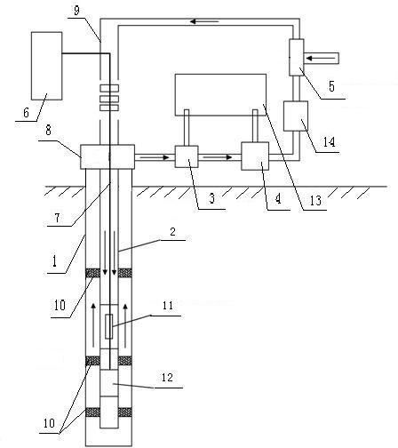
[0020] Below in conjunction with accompanying drawing, the present invention will be further described:

[0021] Such as figure 1 As shown, this laser drilling device includes a surface part and an underground part. The underground part is mainly a drilling device installed in the wellbore, and the surface part is a device for supplying power to the underground drilling device, providing high-pressure gas, and processing bottom lava or dust. . Such as figure 1 As shown, a casing head 8 is installed in the wellhead above the ground to keep the inside of the wellbore 1 closed so as to realize gas circulation. A casing is laid at the surface depth of the wellbore 1, and the casing is a conventional casing with a length of about 100-200m. The conduit 2 extends downward into the wellbore 1 and extends to the bottom of the wellbore 1. The conduit 2 is a coiled pipe or a drill pipe, or it can be a string of other materials with high temperature resistance and certain strength and ...


PUM


Abstract

The invention relates to a laser drilling device, comprising a ground part and an underground part, wherein in an underground pit shaft, a communicated duct extends downwards into the pit shaft from the ground and reaches the bottom of the pit shaft; an MWD (Measurement While Drilling) guide instrument and a laser are arranged in the duct; a cable extends downwards into the pit shaft and is connected with the MWD guide instrument and the laser respectively; a stabilizer is arranged in an annular cavity between the duct and the pit shaft; a sleeve head is arranged at the pit opening on the ground; the duct is connected to an air outlet hole of an air compression booster station through the sleeve head so as to form an air inlet channel; the pit shaft is connected with the sleeve head through a superficial sleeve; the sleeve head is connected with another duct; and the another duct is connected to the air inlet hole of the air compression booster station after passing through a sand remover, a dust remover and a liquid-gas separator so as to form a circulation channel for dust removal, purification and boosting. The laser drilling device disclosed by the invention has high drilling speed, saves the drilling cycle and improves the drilling benefits.

Description

1. Technical field: [0001] The invention relates to a drilling device in the field of petroleum and natural gas engineering, in particular to a laser drilling device which utilizes a high-energy laser to instantly melt deep formation rocks. 2. Background technology: [0002] Deep formation drilling and surface rock drilling technology are mainly realized by breaking soft materials through hard materials. This rock breaking technology is usually called conventional mechanical drilling technology. Rock crushing technology is mainly carried out through the rotation, impact, shearing and other motion modes of rock breaking tools. When these rock-breaking methods break the formation rock and obtain a certain ROP, the self-wearing of the tool will occur, resulting in a large amount of tool consumption. In the deep formation below 1000m, especially in the special high abrasive and high drillability formation, the consumption of tools is very huge. Tooling costs can often account ...

Claims


Application Information

Patent Timeline
Patent Type & Authority Applications(China)
IPC IPC(8): E21B7/00
Inventor 李玮闫铁毕雪亮
Owner NORTHEAST GASOLINEEUM UNIV
Why Eureka
Try Eureka