
Brillouin optical time domain analyzer relevant to chaotic laser

An optical time domain analysis, chaotic laser technology, applied in testing fiber/optical waveguide equipment, instruments, scientific instruments, etc., can solve the difficulties of analyzers, difficulties in locking narrowband detection lasers and narrowband pump lasers, low signal-to-noise ratio, etc. problems, to achieve the effect of improving the signal-to-noise ratio, improving the stability and improving the reliability

Inactive Publication Date: 2012-01-18
WEIHAI BEIYANG PHOTOELECTRIC INFORMATION TECH
View PDF4 Cites 30 Cited by
  • Summary
  • Abstract
  • Description
  • Claims
  • Application Information

AI Technical Summary

Problems solved by technology

[0002] In the field of optical fiber Brillouin optical time domain analyzer, in order to improve the spatial resolution of the sensor, a narrow pulse light source is used, but due to the nonlinear effect of the optical fiber, the incident power of the optical fiber is limited. Therefore, it is necessary to achieve long distance and high spatial resolution. The fiber Brillouin optical time domain analyzer with high efficiency is very difficult. The traditional method of compressing laser pulse width and the method of double pulse pair are difficult to achieve the effect of long-distance spatial resolution less than 1 meter, and the spatial resolution is related to the measurement length. , the signal-to-noise ratio of the system is also low
And the existing technology still has difficulty in locking the narrow-band detection laser and the narrow-band pump laser

Method used


Image

  • Brillouin optical time domain analyzer relevant to chaotic laser
  • Brillouin optical time domain analyzer relevant to chaotic laser
  • Brillouin optical time domain analyzer relevant to chaotic laser

Examples


Embodiment Construction

[0031] The present invention will be further described below in conjunction with the accompanying drawings and embodiments, but not as a basis for limiting the present invention.

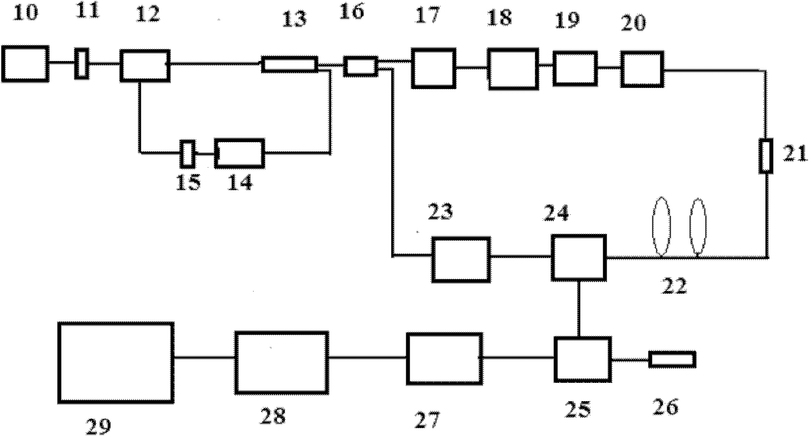
[0032] Example. A chaotic laser-correlated Brillouin optical time-domain analyzer, which is a fiber-optic Brillouin optical time-domain analyzer made of the principle of chaotic laser correlation, the strain of the coherently amplified Brillouin scattered light, the temperature effect and the principle of optical time-domain reflection Analyzer, which uses the same chaotic laser as the probe light source and pump signal light source of the Brillouin optical time domain analyzer.

[0033] It includes a chaotic laser, a second fiber splitter 16, an optical modulator 17, a first erbium-doped fiber amplifier 18, a second adjustable optical attenuator 19, a polarization scrambler 20, a one-way device 21, and a sensing fiber 22 , the second erbium-doped fiber amplifier 23, the second fiber circulator 24,...


PUM

PropertyMeasurementUnit
Center wavelengthaaaaaaaaaa
Spectral bandwidthaaaaaaaaaa

Abstract

The invention discloses a Brillouin optical time domain analyzer relevant to a chaotic laser, which is an optical fiber Brillouin optical time domain analyzer made according to the chaotic laser relevant principle, the coherent amplification Brillouin scattered light, the temperature effect and the optical time domain reflection principle. In the analyzer, the same chaotic laser device serves as the local reference light source and the pump signal light source of the Brillouin optical time domain analyzer. According to the chaotic laser relevant principle, the chaotic laser has an ultra-wide frequency width; signal light and local light are relevantly processed to obtain a high spatial resolution, so that the reliability of the sensor can be effectively improved, the spatial resolution can reach the centimeter level, the number of pump photons entering the sensing optical fiber is increased, the signal to noise ratio of the sensor system is 10dB, and the measurement length of the sensor can reach 50km; and the same chaotic laser device is adopted to serve as the local reference light source and the pump signal light source of the Brillouin optical time domain analyzer, thereby solving the problem of locking a narrow-band detection laser and a narrow-band pump laser, and improving system stability.

Description

technical field [0001] The invention relates to a chaotic laser correlation Brillouin optical time domain analyzer, which belongs to the technical field of distributed optical fiber sensors. Background technique [0002] In the field of optical fiber Brillouin optical time domain analyzer, in order to improve the spatial resolution of the sensor, a narrow pulse light source is used, but due to the nonlinear effect of the optical fiber, the incident power of the optical fiber is limited. Therefore, it is necessary to achieve long distance and high spatial resolution. The fiber Brillouin optical time domain analyzer with high efficiency is very difficult. The traditional method of compressing laser pulse width and the method of double pulse pair are difficult to achieve the effect of long-distance spatial resolution less than 1 meter, and the spatial resolution is related to the measurement length. , the signal-to-noise ratio of the system is also low. Moreover, the prior art...

Claims


Application Information

Patent Timeline
IPC IPC(8): G01B11/16G01K11/32G01K11/322
CPCG01B11/16G01K11/32G01M11/319G01M11/39G01K2011/322G01D5/353G01D5/35364G01K11/322
Inventor 孙忠周张在宣张文生王剑锋
Owner WEIHAI BEIYANG PHOTOELECTRIC INFORMATION TECH
Learn More