
Parallel micro-positioning platform based on driving of piezoelectric ceramic driver and micro-positioning platform system

A technology of micro-positioning platform and piezoelectric ceramics, which is applied to the parts and instruments of the instrument, can solve the problems such as the inability to guarantee the output displacement straightness, the easy damage to the piezoelectric ceramic driver, and the asymmetry of the processing and assembly structure. The effect of suppressing narrow-band ground disturbance, improving displacement output straightness, and being easy to control

Active Publication Date: 2013-04-17
INST OF OPTICS & ELECTRONICS - CHINESE ACAD OF SCI
View PDF4 Cites 2 Cited by
  • Summary
  • Abstract
  • Description
  • Claims
  • Application Information

AI Technical Summary

Problems solved by technology

In order to reduce displacement output coupling, positioning devices at home and abroad all adopt the form of series connection. Chinese patent CN 2621876Y proposes a symmetrically designed flexible guide rail. However, due to processing and assembly errors, structural asymmetry still exists, and the output displacement Straightness is still not guaranteed
Chinese patent CN 2706835Y proposes a planar three-degree-of-freedom positioning platform. On the degree of freedom where two piezoelectric actuators are installed, if the two piezoelectric ceramic actuators output different displacements, one of the piezoelectric ceramic actuators will likely It is separated from the driven moving platform; the piezoelectric ceramic driver directly acts on the moving platform. When the piezoelectric ceramic driver in the direction perpendicular to it has a displacement output, the driver is subjected to bending moment and shear force, and the piezoelectric ceramic driver is easily damaged. ceramic driver
U.S. Patent US20030051331A1 proposes a flexible positioning platform using dual piezoelectric actuators on a single degree of freedom. The output displacement of this positioning platform has good linearity, but it adopts a slot-type series structure. In order to make the X and Y directions The displacement output has good linearity, and two piezoelectric ceramic drivers are required in each direction, which increases the cost; at the same time, the positioning error of the positioning platform adopting a series structure has a cumulative effect on each degree of freedom, and the positioning accuracy is limited.

Method used


Image

  • Parallel micro-positioning platform based on driving of piezoelectric ceramic driver and micro-positioning platform system
  • Parallel micro-positioning platform based on driving of piezoelectric ceramic driver and micro-positioning platform system
  • Parallel micro-positioning platform based on driving of piezoelectric ceramic driver and micro-positioning platform system

Examples


Embodiment Construction

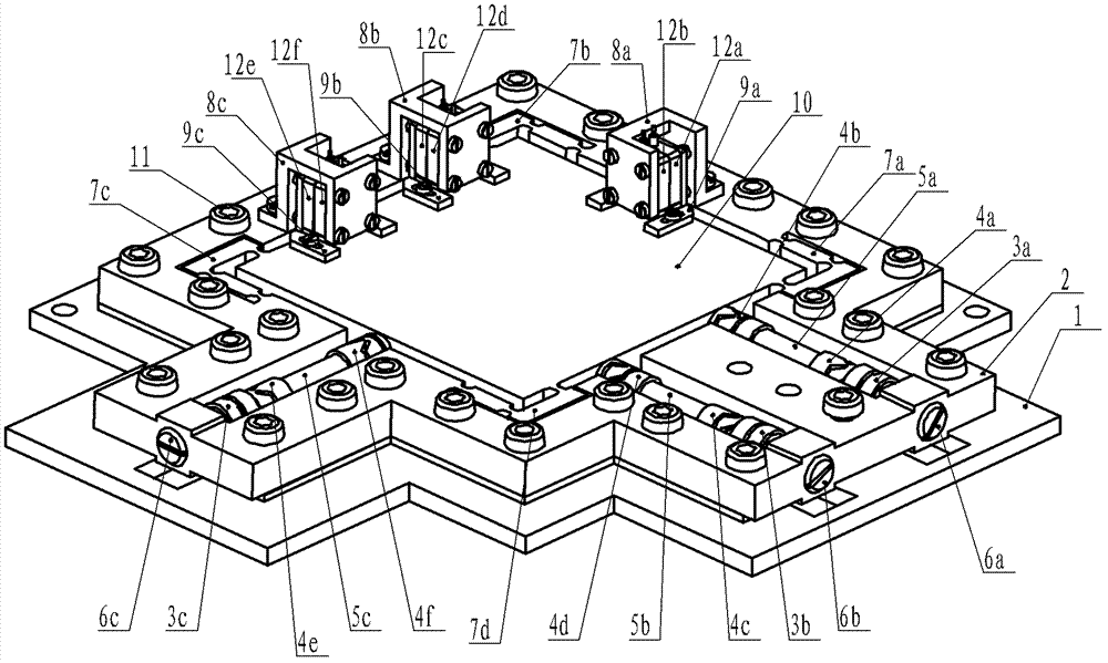
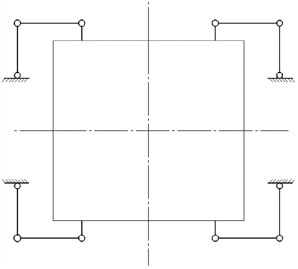
[0025] Since the present invention adopts a parallel structure, the three drivers act on the moving platform at the same time, and the influence of the structural asymmetry of the platform caused by processing and assembly errors on the straightness of the displacement output can be eliminated through closed-loop control; the uniquely designed piezoelectric ceramic driver The tight spring can make the driver always be pressed on the moving platform; the universal hinge can prevent the piezoelectric ceramic driver from breaking due to the bending moment.

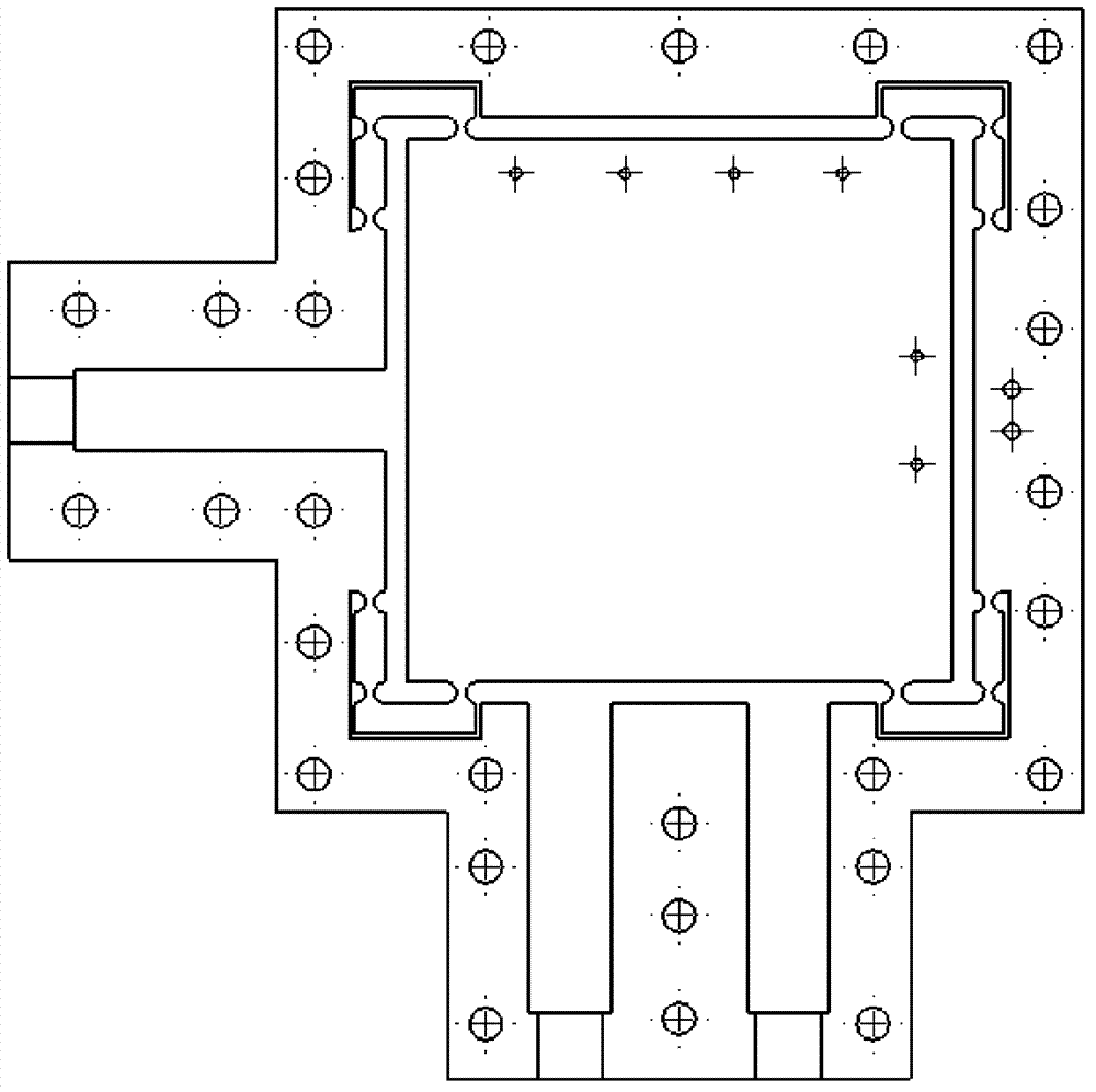
[0026] Such as figure 1 As shown, the parallel micro-positioning platform driven by a piezoelectric ceramic driver of the present invention is composed of a micro-motion stage 2 and a substrate 1 , and the micro-motion stage 2 is fixed on the substrate 1 by a plurality of set screws 11 . The micro-movement platform 2 includes a moving platform 10 in the middle and four flexible hinges 7a, 7b, 7c, 7d located at the four corner...


PUM


Abstract

The invention relates to a parallel micro-positioning platform based on the driving of piezoelectric ceramic drivers and a system, which comprises a micropositioner, a baseplate and a control system, wherein the micropositioner comprises a movable platform and four flexible hinges, a single piezoelectric ceramic driver and a pair of side-by-side piezoelectric ceramic drivers are respectively arranged at the two adjacent sides of the movable platform, one end of each piezoelectric ceramic driver and the movable platform are connected through a universal hinge, the other end of each piezoelectric ceramic driver is connected with a pre-tightening spring through the other universal hinge, and the pre-tightening spring is pre-tightened through a bolt; a capacitance sensor is respectively arranged on the upper surface of the movable platform along the axis direction of each piezoelectric ceramic driver; and one capacitance sensor is positioned on a sensor bracket fixed at the outer side of the micropositioner, the other capacitance sensor is positioned on the other sensor bracket fixed on the upper surface of the movable platform, and computer closed-loop control is adopted. Through theparallel micro-positioning platform and system, the displacement straightness accuracy and the positioning precision are effectively improved, coupling is eliminated, driver separation is avoided, and piezoelectric drivers are protected. By adopting an LQG (Linear Quadratic Gaussian) algorithm of an augmented noise model, narrowband foundation disturbance is effectively inhibited, and the positioning precision is improved.

Description

technical field [0001] The invention relates to a micro-positioning platform technology, in particular to a parallel micro-positioning platform driven by a piezoelectric ceramic driver and a micro-positioning platform system, which can be used in occasions requiring high-precision positioning such as electron microscopy and optical alignment. Background technique [0002] The micro-positioning platform can be used in occasions that require high-precision positioning, such as electron microscopy, optical alignment, etc., especially for occasions that have high requirements for the straightness of output displacement. In order to reduce displacement output coupling, positioning devices at home and abroad all adopt the form of series connection. Chinese patent CN 2621876Y proposes a symmetrically designed flexible guide rail. However, due to processing and assembly errors, structural asymmetry still exists, and the output displacement Straightness is still not guaranteed. Chin...

Claims


Application Information

Patent Timeline
Patent Type & Authority Patents(China)
IPC IPC(8): G12B5/00
Inventor 舒强施宁平饶学军凡木文
Owner INST OF OPTICS & ELECTRONICS - CHINESE ACAD OF SCI
Learn More