Hydrodynamic deep drawing equipment for forming deep cavity parts

A technology of liquid-filled deep drawing and forming equipment, which is applied in the fields of liquid-filled deep drawing and forming hydraulic presses and special technical equipment for sheet metal liquid-filled deep drawing and forming. It can solve the problems of surface and internal damage of formed parts, complex shape and structure of sheet metal parts Problems such as the loss of service life of the rubber bag, to achieve the effect of good surface quality of parts, avoid oil pollution, and reduce use

Inactive Publication Date: 2012-01-25
CHENGDU AIRCRAFT INDUSTRY GROUP
View PDF7 Cites 22 Cited by
  • Summary
  • Abstract
  • Description
  • Claims
  • Application Information

AI Technical Summary

Problems solved by technology

The falling pressure process is a traditional method for forming complex sheet metal parts in the sheet metal process. Due to the large noise pollution in the forming process of this process, the manual trimming workload is large, the forming quality is not easy to control, and the surface and internal damage of the formed parts are serious. It cannot meet the forming requirements of such parts. A considerable part of the complex sheet metal parts formed by the drop pressure process can be formed by the rubber bag hydraulic method. However, there are still quite a few sheet metal parts with very complicated shapes and structures such as negative pull Necked parts with a mold angle and a deep drop, due to the deformation of the rubber bag itself and the sealing requirements under high pressure, such parts cannot be formed by a high-pressure rubber bag hydraulic press, even if the size of individual parts is within the allowable range of the forming limit of the equipment , and no one dares to make a bold attempt at the cost of losing the service life of the rubber bag. At present, the only way to solve this kind of process problem is to divide the parts and change the design.

Method used


Image

  • Hydrodynamic deep drawing equipment for forming deep cavity parts
  • Hydrodynamic deep drawing equipment for forming deep cavity parts
  • Hydrodynamic deep drawing equipment for forming deep cavity parts

Examples


Embodiment Construction

[0026] The technical solutions of the present invention will be further described below in conjunction with the accompanying drawings and specific implementation examples.

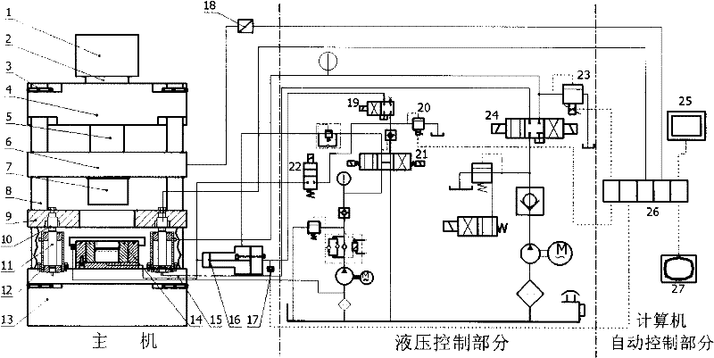
[0027] figure 1It shows a schematic diagram of the overall structure of a deep cavity part liquid-filled deep-drawing forming equipment of the present invention. The deep-cavity liquid-filled deep-drawing equipment includes three main components: the main engine, the hydraulic control part and the computer automatic control part, the main engine It mainly includes oil tank 1, main cylinder 2, round nut 3, upper platform 4, main cylinder piston 5, main slider 6, transition block 7, column 8, blank holder slider 9, force sensor 10, press piston 11, press Side cylinder 12, lower platform 13, ultra-high pressure liquid-filled chamber 14, edge-pressing fixed plate 15, booster cylinder 16, pressure sensor 17, grating ruler 18. Upper platform 4, column 8 and lower platform 13 form hydraulic machine frame, master...


PUM


Abstract

The invention relates to hydrodynamic deep drawing equipment for forming deep cavity parts, which is capable of deep drawing the deep cavity parts with complicated shapes such as necking-type parts with negative draft angles. The equipment is formed by three parts, i.e. a host machine, a hydraulic control system and an automatic control system of a computer. The host machine is a hydraulic machine with three beams and four columns; the hydraulic control system provides motion power to the host machine and mainly comprises two main loops, i.e. a side pressing control loop and a charging chamber control loop; and the automatic control system of the computer is used for collecting data of a displacement sensor and a pressure sensor in real time, accurately controlling and recording formed parameters, and also accurately controlling pressure according to a set curve. The equipment provided by the invention can be used for forming the parts which cannot be formed by a traditional forming process or can be formed only by a plurality of processes; has the advantages of high forming accuracy, good surface quality of the parts, high die fitting degree and the like; and has the characteristics of simplicity and convenience in operation, high control accuracy, high universality, high automation degree and the like.

Description

technical field [0001] The invention relates to a sheet material liquid-filled deep drawing forming equipment, in particular to a liquid-filled deep drawing forming hydraulic machine for deep cavity complex parts, which belongs to the special technical equipment for sheet material liquid-filled deep drawing forming. Background technique [0002] In manufacturing industries such as aviation, aerospace, automobiles, and electrical appliances, some complex sheet metal parts are often encountered, especially those with complex shapes, large surface changes, and deep drop pressure parts. The falling pressure process is a traditional method for forming complex sheet metal parts in the sheet metal process. Due to the large noise pollution in the forming process of this process, the manual trimming workload is large, the forming quality is not easy to control, and the surface and internal damage of the formed parts are serious. It cannot meet the forming requirements of such parts. ...

Claims


Application Information

Patent Timeline
Patent Type & Authority Applications(China)
IPC IPC(8): B21D26/021
Inventor 袁胜许旭东李光俊
Owner CHENGDU AIRCRAFT INDUSTRY GROUP
Why Eureka
Try Eureka