Staggered-parallel-type aluminum alloy finned tube evaporator

A finned tube and aluminum alloy technology, which is applied in the field of heat exchangers and heat transfer, can solve the problems of slowing down the cooling speed, slow cooling, and inconsistent refrigerant temperature, so as to speed up the cooling speed, avoid large temperature rise, reduce The effect of mutual influence

Inactive Publication Date: 2012-01-25
贾凤华
View PDF0 Cites 2 Cited by
  • Summary
  • Abstract
  • Description
  • Claims
  • Application Information

AI Technical Summary

Problems solved by technology

[0002] The row-and-tube evaporator used in the existing refrigeration system is mainly composed of finned tubes and bent tubes. Most of them use seamless steel tubes or copper tubes, which are bent, welded and supported on site. This method has a long construction period on site. , Welding, cleaning, pressing and inspection are troublesome, and the quality is difficult to guarantee
Steel pipes are prone to corrosion, many system failures, high cost of copper pipes
The finned tubes of the existing tube-and-tube evaporator are arranged side by side, and multiple finned tubes are on the same plane. This structure has slow cooling and less heat exchange surface, and two adjacent finned tubes will affect each other, reducing slow cooling rate
The existing row-and-tube evaporator adopts a serial form. When it is used in a large-scale cold storage, due to the long length of the pipeline, the temperature of the refrigerant in the finned tube increases with the increase of the distance passed, resulting in a large increase in the temperature of the refrigerant in the finned tube. The temperature of the cold storage is inconsistent, which reduces the heat transfer effect and the refrigeration effect is not ideal, resulting in uneven temperature in the large cold storage

Method used


Image

  • Staggered-parallel-type aluminum alloy finned tube evaporator
  • Staggered-parallel-type aluminum alloy finned tube evaporator

Examples


Embodiment Construction

[0012] The present invention will now be described in further detail with reference to the accompanying drawings. These drawings are all simplified schematic diagrams, and only illustrate the basic structure of the present invention in a schematic manner, so they only show the structures related to the present invention.

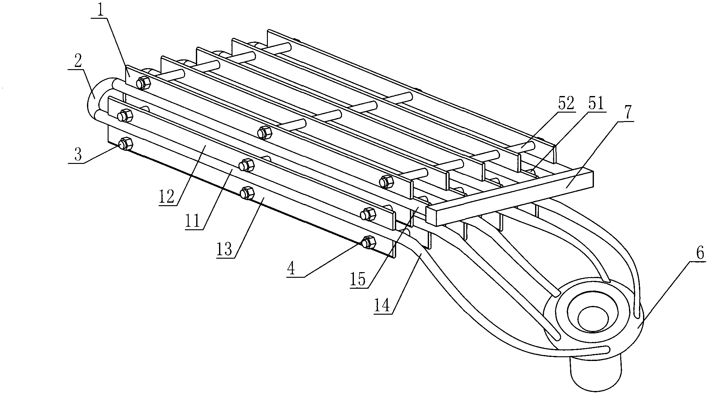
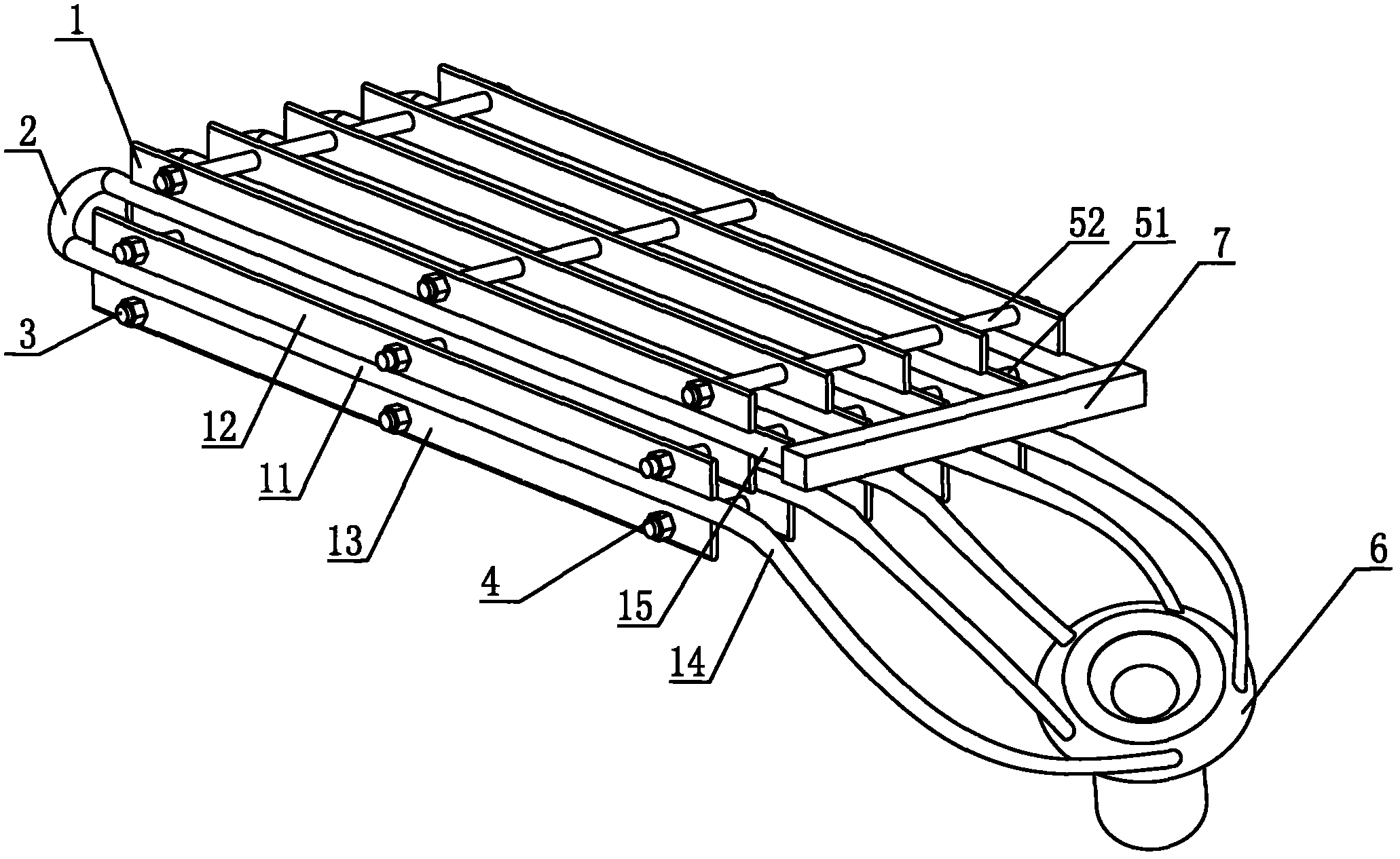
[0013] figure 1 It is a schematic structural diagram of the preferred embodiment of the staggered and parallel type aluminum alloy finned tube evaporator of the present invention. A staggered parallel type aluminum alloy finned tube evaporator includes a plurality of finned tubes 1 and bent tubes 2. The fin tube 1 includes a light tube 11 through which the refrigerant passes, and upper fins 12 and lower fins 13 arranged on the outer wall of the light tube. The upper fins 12 and the lower fins 13 are respectively provided with installation holes, and the installation holes penetrate through them. The lead screw 3, the lead screw 3 between the adjacent finned...


PUM


Abstract

The invention relates to a staggered-parallel-type aluminum alloy finned tube evaporator which comprises a plurality of finned tubes and a bend tube; the plurality of finned tubes are arrayed in parallel; the two adjacent finned tubes are staggered up and down; the upper fins of the lower finned tubes are corresponding to the lower fins of the upper finned tubes; two finned tubes at intervals are at the same level; two ends of the bend tube are respectively connected with two finned tubes, thus a parallel unit is formed; two finned tubes of each parallel unit are respectively a liquid inlet tube and a liquid outlet tube, and are provided with a liquid distributor; the liquid distributor is provided with a liquid inlet and liquid outlets the number of which is corresponding to the number of the liquid inlet tubes; the liquid inlet tubes of each parallel unit are communicated with a refrigerant liquid inlet pipeline through a liquid distributor; and the liquid outlet tubes of each parallel unit are communicated with the refrigerant liquid inlet pipeline. According to the invention, through adopting the up and down staggered array mode of the finned tubes, the mutual influence between the adjacent finned tubes is reduced, the refrigeration speed is accelerated, more uniform refrigeration is realized through the parallel connection mode, the frosting on the fins is uniform.

Description

technical field [0001] The invention relates to the technical field of heat exchangers and heat transfer, in particular to a staggered parallel type aluminum alloy fin tube evaporator. Background technique [0002] The tube-type evaporators used in the existing refrigeration system are mainly composed of finned tubes and elbows. , Welding, cleaning, pressure inspection is troublesome, and the quality is difficult to guarantee. Steel pipes are easy to corrode, there are many system failures, and the cost of copper pipes is high. The finned tubes of the existing tube-type evaporator are arranged side by side, and a plurality of finned tubes are in the same plane. This structure has slow cooling and less heat exchange surface, and two adjacent finned tubes will affect each other, reducing the cost. Slow cooling speed. The existing tube-type evaporators are in series. When used in large-scale cold storage, the temperature of the refrigerant in the finned tube increases with t...

Claims


Application Information

Patent Timeline
Patent Type & Authority Applications(China)
IPC IPC(8): F25B39/02
Inventor 王滔贾凤华
Owner 贾凤华
Why Eureka
Try Eureka