Two-path loop-locked resonant mode optical gyro

An optical gyroscope, resonant technology, applied in the field of optical sensing and signal detection, can solve the problems of low output linearity of gyroscope, failure to suppress reciprocity noise well, narrow loop bandwidth, etc., so as to improve reciprocity , improve linearity and dynamic range, reduce the effect of optical Kerr noise

Active Publication Date: 2012-01-25
ZHEJIANG UNIV
View PDF6 Cites 15 Cited by
  • Summary
  • Abstract
  • Description
  • Claims
  • Application Information

AI Technical Summary

Problems solved by technology

[0003] The most common locking method in ROG is single-channel locking, that is, the center frequency of the laser is locked on one of the resonant frequencies, and the output of the other channel is the gyro signal output. However, the problem with single-channel locking is that the l

Method used


Image

  • Two-path loop-locked resonant mode optical gyro
  • Two-path loop-locked resonant mode optical gyro
  • Two-path loop-locked resonant mode optical gyro

Examples


Embodiment Construction

[0021] The present invention will be described in detail below in conjunction with the embodiments and accompanying drawings, but the present invention is not limited thereto.

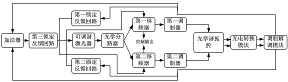
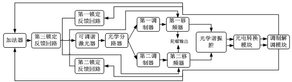
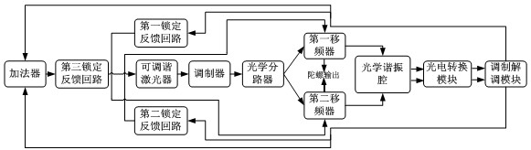
[0022] Such as figure 1 As shown, the double-channel closed-loop resonant optical gyro type I includes a tunable laser, an optical splitter, a first frequency shifter, a second frequency shifter, a first modulator, a second modulator, an optical resonant cavity, The optical system composed of the photoelectric conversion module, and the processing circuit composed of the modulation and demodulation module, the first feedback locking module, the second feedback locking module and the third feedback locking module, the tunable laser is connected with the optical splitter, and the optical splitter The device is connected with the first frequency shifter and the second frequency shifter respectively, the first frequency shifter, the first modulator, and the optical resonant cavity are connected in sequence...


PUM


Abstract

The invention discloses a two-path loop-locked resonant mode optical gyro, which comprises an optical system comprising a tunable laser, an optical splitter, optical frequency shifters, optical modulators, an optical resonant cavity, a photoelectric conversion module and the like, and a processing circuit consisting of a demodulation module and feedback lock modules. In the optical gyro, two paths of signals with gyro rotation information are extracted by the processing circuit, and the frequency shift quantities of two paths of frequency shifters are respectively changed through two feedbacklock modules; simultaneously the two paths of signals are added together and then locked at the central point of clockwise and anticlockwise optical path resonant frequencies of the resonant cavity after the laser frequency is controlled by a third feedback lock module; and finally the frequency shift quantity outputs of the two paths of frequency shifters are subtracted each other to obtain a gyro signal. The two-path loop-locked resonant mode optical gyro disclosed by the invention is conductive to improving the reciprocity of the resonant mode optical gyro and better eliminating reciprocity noise, is conductive to improving the linear and the dynamic range of a gyro system, and is conductive to reducing the optical power difference of clockwise and anticlockwise light paths in the cavity and reducing optical Kerr noise.

Description

technical field [0001] The invention relates to the technical field of optical sensing and signal detection, in particular to a double-channel closed-loop resonant optical gyroscope. Background technique [0002] Resonator Optic Gyro (ROG) is a high-precision miniature inertial sensor that uses the optical Sagnac effect to detect rotation. The resonant optical gyro without vibrating parts has the advantages of miniaturization, high precision and anti-vibration. Compared with Micro Electro Mechanical Systems (MEMS) and Fiber Optic Gyroscopes (Interferometric Fiber Optical Gyroscope, IFOG), ROG will have greater advantages. [0003] The most common locking method in ROG is single-channel locking, that is, the center frequency of the laser is locked on one of the resonant frequencies, and the output of the other channel is the gyro signal output. However, the problem with single-channel locking is that the loop bandwidth is narrow, and the gyro The output linearity is smal...

Claims


Application Information

Patent Timeline
IPC IPC(8): G01C19/66G01C19/68
Inventor 金仲和张顾洪马慧莲
Owner ZHEJIANG UNIV
Why Eureka
Try Eureka