Grating-based phase difference wavefront sensor

A wavefront sensor and phase difference technology, applied in instruments, scientific instruments, measurement optics, etc., can solve the problems of difficulty in accurate image acquisition, influence of light intensity distribution information, influence of detection accuracy, etc. Application value, application reliable effect

Active Publication Date: 2012-01-25
INST OF OPTICS & ELECTRONICS - CHINESE ACAD OF SCI
View PDF3 Cites 32 Cited by
  • Summary
  • Abstract
  • Description
  • Claims
  • Application Information

AI Technical Summary

Problems solved by technology

Since the output image of the CCD imaging detector has certain noise, and the CCD imaging detector has a relatively sensitive light intensity range, when the light intensity of the spot is weak, it is affected by the signal-to-noise ratio of the output image and the sensitivity of the CCD imaging detector. Affected by the CCD, the CCD cannot obtain the light intensity distribution information of the diffraction spot with a higher order, the high-frequency information of the restoration aberration will be lost, and the detection accuracy will be affected to a certain extent
If the distorted wavefront to be measured contains not only large-scale, slowly changing low-spatial-frequency optical aberrations, but also high-spatial-frequency aberrations caused by optical component processing, the distorted wavefront will cause focal plane position, defocus

Method used


Image

  • Grating-based phase difference wavefront sensor
  • Grating-based phase difference wavefront sensor
  • Grating-based phase difference wavefront sensor

Examples


Embodiment Construction

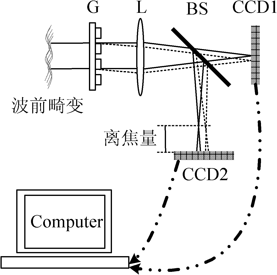
[0022] Such as figure 1 As shown, the grating type phase difference wavefront sensor includes: grating G, lens L, beam splitter BS, CCD imaging detectors CCD1 and CCD2, and computer C. The grating G is used to divide the incident beam into multiple beams with different intensities and consistent phases; the lens L is mainly used to converge the beams modulated by the grating G; the beam splitter BS makes the converged beams image on the photosensitive surfaces of CCD1 and CCD2 respectively Different detection areas; and use imaging detectors CCD1 and CCD2 to collect the light intensity distribution of the focal plane and defocused plane respectively; finally, the computer system C is mainly used to collect the image data output by the CCD imaging detectors CCD1 and CCD2, according to the detected position The position of the focal plane and the light intensity distribution information of the diffraction spot at the corresponding position away from the focal plane are calculated ...


PUM


Abstract

The invention discloses a grating-based phase difference wavefront sensor which comprises a grating, a lens, a spectroscope, a CCD (Charge Coupled Device) imaging detector, a computer and the like, wherein a parallel light beam containing wavefront distortion is directly irradiated onto the surface of the grating; and the light beam is divided into multiple beams of light with different intensities and same phase after being transmitted by the grating and is imaged on a CCD photosensitive surface by the lens. According to two or multiple grating diffraction spots, the light intensity distribution of the spots can be more accurately calculated by a corresponding algorithm. According to focal plane and defocusing surface light intensity distribution, the computer can restore to obtain wavefront distortion information to be detected. In the grating-based phase difference wavefront sensor, the CCD imaging detector can be used for collecting the high-frequency ingredient of the light intensity distribution which can not be measured in the common condition, the detection precision of the phase difference wavefront sensor is effectively improved, and the phase difference wavefront sensor has obvious advantages in the fields of optical detection, adaptive optics, high-resolution imaging and the like.

Description

technical field [0001] The invention relates to a phase difference-based wavefront sensor, in particular to a grating-based phase difference wavefront sensor. Background technique [0002] Due to its simple structure, no special requirements on the light source and high measurement accuracy, the phase difference wavefront sensor is used as a wavefront sensor in the field of adaptive optics. Gonsalves R A in "Wavefront sensing by phase retrieval", in Applications of Digital Image Processing III, Proc. SPIE, vol.207, 1979 and "Phase retrieval and diversity in adaptive optics" Opt Eng, Vol.21, 829-832, 1982 In the two articles, it is proposed to add a defocus aberration of known size to the wavefront to be measured, and accurately measure the focal plane light intensity distribution and multiple light intensity distributions located on different defocus planes. Based on the least squares estimation, the GS The iterative algorithm accurately restores the distorted wavefront in ...

Claims


Application Information

Patent Timeline
IPC IPC(8): G01J9/00
Inventor 罗群饶长辉黄林海顾乃庭
Owner INST OF OPTICS & ELECTRONICS - CHINESE ACAD OF SCI
Why Eureka
Try Eureka