
Method for measuring discharged quantities of greenhouse gases of flowing water body

A technology of greenhouse gas and measurement methods, which is applied in the direction of testing water, material inspection products, etc., can solve the problem of underestimating the emission flux, and achieve the effect of convenient operation, less external interference, and accurate emission situation.

Inactive Publication Date: 2012-01-25
INST OF SOIL SCI CHINESE ACAD OF SCI
View PDF12 Cites 26 Cited by
  • Summary
  • Abstract
  • Description
  • Claims
  • Application Information

AI Technical Summary

Problems solved by technology

However, bubbling emissions have strong temporal and spatial variability characteristics, because bubbling is the main emission mode of methane, so this method will underestimate CO 2 and N 2 O emission flux
This method is also not suitable for the case of flowing water bodies

Method used


Image

  • Method for measuring discharged quantities of greenhouse gases of flowing water body
  • Method for measuring discharged quantities of greenhouse gases of flowing water body
  • Method for measuring discharged quantities of greenhouse gases of flowing water body

Examples


Embodiment 1

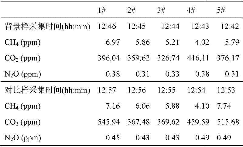
[0024] Example 1. This experiment was carried out in Jurong River. The purpose of the experiment was to determine the river's greenhouse gas emission rate.

[0025] 1 Make 5 floating sampling boxes: the box is a cylinder made of 3mm thick PVC, the bottom radius is 15cm, the height is 12cm, and the outside of the box is wrapped with a ring-shaped foam material with an outer diameter of 25cm and an inner diameter of 15cm. The upper two ends of the box are connected with a fixed rope about 1 meter in length. On the upper side of the box, there is a sampling hole with a sampling pad, and a vent hole with a radius of 5mm, wrapped with a layer of tin foil for heat insulation.

[0026] 2 The sampling boxes are numbered 1#, 2#, 3#, 4#, 5# in sequence. Two adjacent boxes are connected by a fixed rope. In addition to the 1# box connected with the 2# box, the other end of the fixed rope is placed in the hand by an extension rope (10 meters). First put the 5# box lightly above the water surfa...

Embodiment 2

[0034] Example 2. This experiment was carried out at the confluence of the Qinhuai River and Jurong River. The purpose of the experiment was to determine the N 2 The impact of O emissions.

[0035] This experiment uses the present invention to determine river N 2 Measure the physical and chemical properties of river water at the same time as O emission flux, such as dissolved N 2 O concentration, dissolved DO, NO 3 - , NH 4 + , TN, pH, Cl -1 , SO 4 2- , DOC, water temperature, air temperature, flow rate and other factors. The experimental methods and steps are the same as in Example 1. The calculation results of N2O emission rate of each sampling box are shown in Table 3.

[0036] Table 3 Measurement table of N2O emission rate of each sampling box at the confluence of Jurong River and Qinhuai River

[0037]

[0038] Therefore, the N2O emission rates of Jurong River and Qinhuai River before the confluence were 1.50 and 1.73 μmol m, respectively -2 h -1 , Qinhuai River N after confluenc...


PUM


Abstract

The invention discloses a method for measuring discharged quantities of greenhouse gases of a flowing water body. The method comprises the following steps of: (1) making a plurality of floating sampling boxes; (2) connecting the floating sampling boxes two by two through fixed ropes, placing the connected floating sampling boxes on a water surface, and sealing ventilating holes by using soft plugs; (3) extracting gases from the floating sampling boxes by using a needle cylinder, placing the extracted gases into a vacuum bottle as background samples, and recording a sampling time of each box body; (4) dragging the box bodies and drifting the box bodies along water, pulling the floating sampling boxes back to the shoreside, extracting contrast samples from the floating sampling boxes again by using the needle cylinder, and recording the sampling time of each floating sampling box; (5) taking the background sample and the contrast sample of each floating sampling box back to a laboratory, and measuring concentrations of CO2, CH4 and N2O of the samples; and (6) calculating a discharge rate of each greenhouse gas of the water body. By the method for long-time systematic measurement, estimation for nitrogen income and outgoing, estimation for a discharged flux of each greenhouse gas of the water body and evaluation for emission reduction measures can be realized according to a result. The method adapts for characteristics of the flowing water body; and the greenhouse gases on the water surface can be acquired conveniently, quickly and accurately.

Description

Technical field [0001] The invention relates to a method for measuring greenhouse gas emissions from a flowing water body, which is suitable for water-gas interface CO in a flowing state 2 , CH 4 , N 2 Measurement of greenhouse gas emissions such as O. Background technique [0002] Greenhouse gas refers to the gas that causes the greenhouse effect in the earth’s atmosphere, mainly including CO 2 , CH 4 , N 2 O and water vapor, etc. Infrared rays are easily absorbed by greenhouse gases in the atmosphere when they are scattered into space, causing a large part of the radiant energy to return to the surface of the earth, leading to a rise in global temperature. This warming effect is called the greenhouse effect. With CO 2 Compared to CH 4 It stays in the atmosphere for longer time, has stronger infrared absorption capacity, and its warming potential is about CO 2 23 times. The warming effect of N2O is about CO 2 298 times. It is estimated that the CO in the atmosphere 2 The volum...

Claims


Application Information

Patent Timeline
Patent Type & Authority Applications(China)
IPC IPC(8): G01N33/18
Inventor 夏永秋颜晓元李跃飞李晓波
Owner INST OF SOIL SCI CHINESE ACAD OF SCI
Learn More