Doherty power amplifier with high efficient broadband

A power amplifier and high-efficiency technology, applied to power amplifiers, improving amplifiers to improve efficiency, etc., to achieve high efficiency, high-efficiency load modulation, and reduce the effect of impedance conversion ratio

Inactive Publication Date: 2012-01-25
UNIV OF ELECTRONICS SCI & TECH OF CHINA
View PDF3 Cites 23 Cited by
  • Summary
  • Abstract
  • Description
  • Claims
  • Application Information

AI Technical Summary

Problems solved by technology

Due to the nonlinear nature of power amplifiers, designing a transmitter with high power efficiency becomes a great challenge

Method used


Image

  • Doherty power amplifier with high efficient broadband
  • Doherty power amplifier with high efficient broadband
  • Doherty power amplifier with high efficient broadband

Examples


Embodiment 1

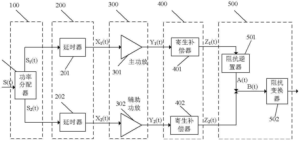
[0021] The broadband high-efficiency Doherty power amplifier provided by the present invention, as figure 2 shown, including:

[0022] The power distribution unit 100 includes a power divider 101, and the power divider 101 decomposes the baseband input signal into two signals with equal power and equal phase. The unit includes at least one power splitter 101 .

[0023] The radio frequency input signal S(t)=a(t)cos(ωt+θ) is input to the power splitter 101 for power distribution processing, and the power splitter 101 performs in-phase separation on the radio frequency input signal S(t) based on the power distribution processing technology, which The specific separation method is consistent with the traditional Wilkinson power distribution method, which is a known technology, so it will not be described in detail here. The power divider 101 should include a Wilkinson power divider, and the separated two-way radio frequency signals are signal S 1 (t) and S 2 (t). S 1 (t) an...

Embodiment 2

[0046] The structure of the Doherty power amplifier is the same as in Embodiment 1.

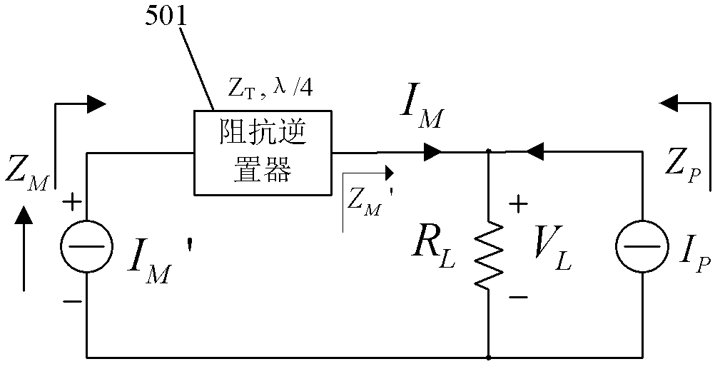
[0047] The main power amplifier 301 has high efficiency when backing off by 3dB. The load impedance is Z M 110 ohms, Z M into 110 ohms. For a traditional 50 ohm impedance inverter 501 then R L Need to be 22.7, now the impedance conversion ratio is r=110 / 22.7=4.8, and for the improved structure of r=4, then the load impedance of impedance inverter 501 is 55 ohms and R L is 27.5. This enables wideband performance while achieving high efficiency. When the power of the main power amplifier 301 is saturated, its load needs to be 50 ohms, mainly for the purpose of extracting its performance characteristics with a standard test system alone. Therefore the port impedance of the impedance inversion unit is required And by active modulation Then I P / I M =1.2, at this time it can be calculated that the impedance of the auxiliary power amplifier 302 is about 2.2 / 1.2*R L = 50.4 ohms. The cha...

Embodiment 3

[0049] The structure of the Doherty power amplifier is the same as in Embodiment 1.

[0050] The main power amplifier 301 has high efficiency when backing off by 3dB. The load impedance is Z M 130 ohms, Z M into 130 ohms. For a traditional 50 ohm impedance inverter 501 then R L It needs to be 19.2, and now the impedance conversion ratio is r=130 / 19.2=6.8, and for the improved structure of r=4, the impedance inverter 501 of 65 ohms and R L is 32.5. This enables wideband performance while achieving high efficiency. When the power of the main power amplifier 301 is saturated, its load needs to be 50 ohms, mainly for the purpose of extracting its performance characteristics with a standard test system alone. Therefore the port impedance of the impedance inversion unit is required And by active modulation Then I P / I M =1.6, at this time it can be calculated that the impedance of the auxiliary power amplifier 302 is about 2.6 / 1.6*R L = 52.8 ohms. The characteristic i...


PUM


Abstract

The invention provides a Doherty power amplifier capable of realizing high efficiency in a wider frequency range. The Doherty power amplifier comprises a power distribution unit, a delay unit, a signal amplifying unit, a parasitic compensation unit and a power synthesizing unit; the signal amplifying unit comprises a main power amplifier and an auxiliary power amplifier; the power synthesizing unit comprises an impedance inverse device and an impedance converter; when the auxiliary power amplifier does not work, the load impedance of the main power amplifier is 110 to 130 ohms; and the impedance conversion rate of the impedance reverse device satisfied by the characteristic impedance of the impedance inverse device is 4. According to the power amplifier provided by the invention, the power amplifier has a high efficiency when the load impedance of the main power amplifier is 110 to 130 ohms and the main power amplifier withdraws 3-4 dB; as the characteristic impedance of the impedance reverse device is increased, the impedance reverse ratio of the impedance reverse device is controlled to be 4, thereby obtaining the high efficient Doherty power amplifier capable of satisfying the broadband requirement.

Description

technical field [0001] The invention belongs to the technical field of wireless communication, and relates to a transmitting device of the wireless communication technology, in particular to a structure of a broadband high-efficiency Doherty power amplifier. Background technique [0002] The Doherty technique was proposed by Doherty in 1936. Doherty technology is a commonly used technology to improve the efficiency of power amplifiers. The block diagram of its traditional circuit is as follows: figure 1 As shown, the baseband signal is input into the power divider 10, and the power divider 10 utilizes power distribution technology to decompose the radio frequency input signal into two signals with equal power and equal phase; Delay processing to obtain different phases to obtain radio frequency (RF) signals; main power amplifier (carrier amplifier) ​​31 and auxiliary power amplifier (peak amplifier) ​​32 carry out power amplification to two-way radio frequency signals respe...

Claims


Application Information

Patent Timeline
Patent Type & Authority Applications(China)
IPC IPC(8): H03F3/20H03F1/07
Inventor 游飞雷奇何松柏刘家鹏董磊
Owner UNIV OF ELECTRONICS SCI & TECH OF CHINA
Why Eureka
Try Eureka