Broadband reflectors, concentrated solar power systems, and methods of using the same
A power generation system, reflective technology, applied in the field of concentrating solar power generation systems, to achieve the effects of low weight, improved power collection capability, and low cost
- Summary
- Abstract
- Description
- Claims
- Application Information
AI Technical Summary
Problems solved by technology
Method used
Image
Examples
example 1
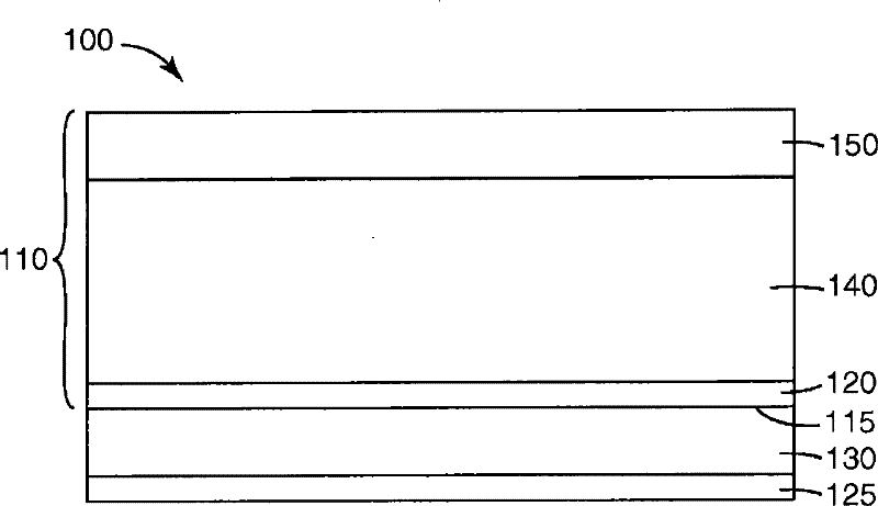
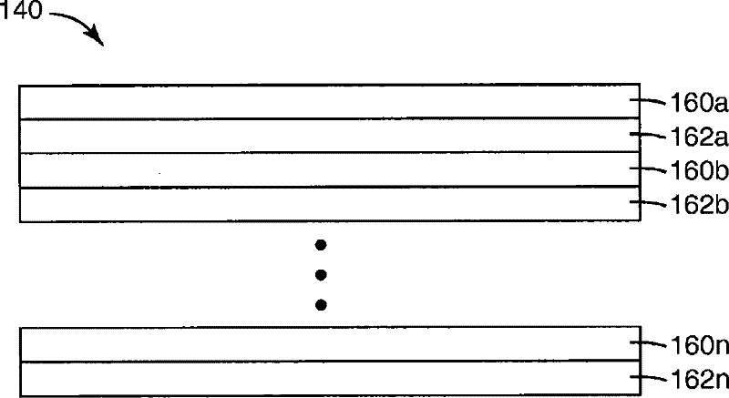
[0127] A UV reflective multilayer optical film was prepared utilizing a first optical layer made of polyethylene terephthalate (PE) obtained from Eastman Chemical (Kingsport, TN) as EASTAPAK 7452 and a second optical layer. PET1) produced from a copolymer of 75% by weight methyl methacrylate and 25% by weight ethyl acrylate (available as PERSPEX CP63 from Ineos Acrylics, Inc. (Memphis, Tenn.)) ( coPMMA1) produced. PET1 and CoPMMA1 were coextruded through a multilayer polymer melt manifold to form a stack of 223 optical layers. The layer thickness profile (layer thickness value) of this UV reflector is tuned to be approximately linear, where the first (thinnest) optical layer is tuned to have an approximately 1 / 4 wavelength optical thickness (refractive index) for 340 nanometer (nm) light. times the physical thickness) and progress toward the thickest layer adjusted to have an optical thickness of about 1 / 4 wavelength thick for 420 nm light. The layer thickness distribution o...
example 2
[0131] A UV reflective multilayer optical film was prepared using a first optical layer produced from PET1 and a second optical layer produced from CoPMMA1. PET1 and CoPMMA1 were coextruded through a multilayer polymer melt manifold to form 223 optical layers. The layer thickness profile (layer thickness values) of this UV reflector is tuned to be approximately linear, with the first (thinnest) optical layer tuned to have about 1 / 4 wavelength optical thickness (refractive index times physical thickness) for 340nm light And progress towards the thickest layer, which is tuned to have an optical thickness about 1 / 4 wavelength thick for 420 nm light. The layer thickness distribution of such films can be tuned to provide improved spectral properties using the shaft rod apparatus taught in US Patent No. 6,783,349 (Neavin et al.) in conjunction with layer distribution information obtained using microscopy techniques.
[0132] In addition to these optical layers, non-optical protecti...
example 3
[0138] A UV reflective multilayer optical film was prepared using a first optical layer produced from PET1 and a second optical layer produced from CoPMMA1. PET1 and CoPMMA1 were coextruded through a multilayer polymer melt manifold to form 223 optical layers. The layer thickness profile (layer thickness values) of this UV reflector is tuned to be approximately linear, with the first (thinnest) optical layer tuned to have about 1 / 4 wavelength optical thickness (refractive index times physical thickness) for 340nm light And progress towards the thickest layer, which is tuned to have an optical thickness about 1 / 4 wavelength thick for 420 nm light. The layer thickness distribution of such films can be tuned to provide improved spectral properties using the shaft-and-rod device taught in US Patent No. 6,783,349 (Neavin et al.) by combining layer distribution information obtained with microscopy techniques.
[0139] In addition to these optical layers, non-optical protective skin...
PUM
 Abstract
Description
Claims
Application Information
 - R&D
- Intellectual Property
- Life Sciences
- Materials
- Tech Scout
- Unparalleled Data Quality
- Higher Quality Content
- 60% Fewer Hallucinations
Browse by: Latest US Patents, China's latest patents, Technical Efficacy Thesaurus, Application Domain, Technology Topic, Popular Technical Reports.
© 2025 PatSnap. All rights reserved.Legal|Privacy policy|Modern Slavery Act Transparency Statement|Sitemap|About US| Contact US: help@patsnap.com


