Infrared thermal imager and method for detecting infrared objective image by using same

A technology of infrared thermal imager and infrared detector, which is applied in the field of infrared thermal imager, can solve the problems of uniform distribution of radiation on the target surface of the detector, great influence on the correction effect, poor correction effect, etc., to achieve real-time and automatic Adaptability, improved detection performance, and high reliability

Active Publication Date: 2012-02-01
NO 717 INST CHINA MARINE HEAVY IND GRP
View PDF6 Cites 21 Cited by
  • Summary
  • Abstract
  • Description
  • Claims
  • Application Information

AI Technical Summary

Problems solved by technology

However, since it is difficult for these reference calibration devices to be close to the temperature of the background at any time, and it is difficult to evenly distribute the radiation emitted by the

Method used


Image

  • Infrared thermal imager and method for detecting infrared objective image by using same
  • Infrared thermal imager and method for detecting infrared objective image by using same
  • Infrared thermal imager and method for detecting infrared objective image by using same

Examples


Example Embodiment

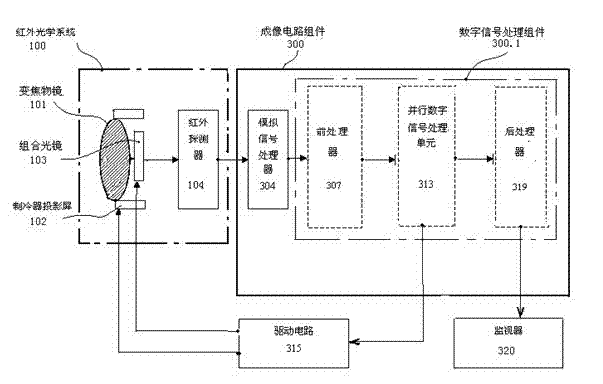
[0046] Example 1: It is an embodiment of an infrared camera product. As attached figure 1 , 2 , 3, 4, it has an infrared optical system 100, an imaging circuit assembly 300, and a drive circuit 315 and a monitor 320; the infrared optical system 100 includes a zoom objective lens 101, which is installed in sequence after the zoom objective lens 101 There are: a refrigerator projection screen 102, a combined light mirror 103 and an infrared detector 104; the imaging circuit assembly 300 includes an analog signal processor 304 and a digital signal processing assembly 300.1; the digital signal processing assembly 300.1 includes sequentially connected The pre-processor 307, the parallel digital signal processing unit 313, and the post-processor 319; the output end of the infrared detector 104 is connected to the analog signal processor 304; the input end of the driving circuit 315 is connected to the parallel digital signal processing unit 313 The output end is connected with the c...

Example Embodiment

[0057] Example 2 : It is the method of detecting infrared object image with the infrared thermal imager of the present invention, such as figure 1 , 2 As shown in, 3 and 4, the infrared thermal imager includes an infrared optical system 100, an imaging circuit assembly 300, a drive circuit 315 and a monitor 320, and the method of detecting an infrared object image includes the following steps:

[0058] A. Power-on: After power-on, after entering the normal working state, the parallel digital signal processing unit 313 works and enters the adaptive non-uniform correction mode;

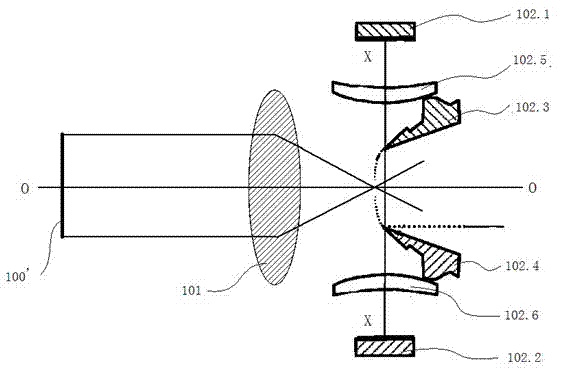
[0059] B. Scene image focusing: In the infrared optical system 100, the scene image is focused on the cooler projection screen 102 to form an intermediate image M;

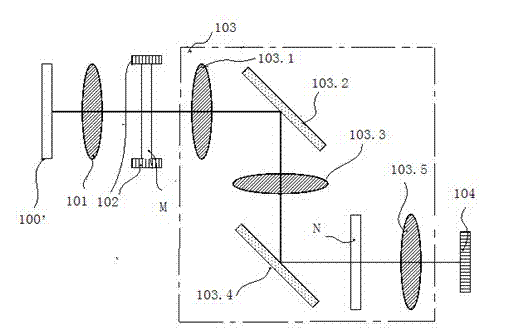
[0060] C. Image scanning: the scanning mirror 103.2 in the infrared optical system 100 scans the intermediate image M, respectively scanning the first thermoelectric cooler 102.1, the scene infrared image and the second thermoelectric cooler 102.2...

Example Embodiment

[0065] Example 3 : The digital information processing and imaging method of the infrared thermal imager of the present invention, such as Figure 4 As shown, the imaging circuit assembly 300 includes an analog signal processor 304 and a digital signal processing assembly 300.1; the digital signal processing assembly 300.1 includes a pre-processor 307, a parallel digital signal processing unit 313, and a post-processor 319 connected in sequence. ; The method of digital information processing and imaging includes the following steps:

[0066] a. Analog signal processing: the analog signal processor 304 amplifies the signal of the infrared detector 104 into an analog signal and converts it into a digital signal;

[0067] b. Pre-processing: the input terminal of the pre-processor (FPGA) 307 is connected to the output terminal of the analog signal processor 304, receives the digital signal after analog-to-digital conversion, and passes each frame of image sequence through the original ...


PUM


Abstract

The invention relates to an infrared thermal imager and a method for detecting an infrared objective image by using the same. The infrared thermal imager comprises an infrared optical system, an imaging circuit component, a driving circuit and a monitor, wherein the infrared optical system comprises a varifocal objective; and a refrigerator projection screen, a combination optical mirror and an infrared detector are sequentially arranged behind the varifocal objective. The method for detecting the infrared objective image by using the infrared thermal imager comprises the following steps of: focusing an image of a scene; scanning the image; focusing, and converting an electric signal; and correcting temperature in real time, and controlling. The invention has the advantages that: the infrared thermal imager is smart in structure, simple and convenient to operate, quite high in reliability and accurate in temperature control; the problem of temperature difference between a reference calibration source and the scene in the prior art is solved; effects of real-time performance and self-adaptation in correction of the current scene are good; the uniformity of the corrected image is guaranteed; a correction effect is greatly improved; and the quality of the image is high.

Description

technical field [0001] The invention relates to an infrared thermal imager and a method for detecting infrared object images thereof, in particular to an infrared thermal imager with an adaptive non-uniform correction device, belonging to the technical field of optical instruments. Background technique [0002] The thermal imaging camera has the characteristics of passive, strong anti-interference, day and night observation, and strong ability to detect fast and small targets. It has become an important part of the photoelectric system in the fields of reconnaissance, monitoring, and target tracking. in the object tracking industry. In practical applications, due to the manufacturing process, the pixels of the infrared detector cannot be completely consistent, resulting in the problem of non-uniformity, which brings difficulties to infrared imaging. Especially for military thermal imaging cameras under complex backgrounds, the impact of non-uniformity is particularly promin...

Claims


Application Information

Patent Timeline
IPC IPC(8): G01J5/12
Inventor 潘德彬张智杰王晨晟洪普
Owner NO 717 INST CHINA MARINE HEAVY IND GRP
Why Eureka
Try Eureka