
Regeneration system for smoke carbon dioxide capture solution

A regeneration system, carbon dioxide technology, applied in the direction of inorganic chemistry, carbon compounds, chemical instruments and methods, etc., can solve the problems of large steam consumption, solution circulation pump cavitation, affecting solution flow, etc., to improve heat exchange efficiency, reduce gas The effect of reducing the risk of corrosion and improving the desorption rate

Active Publication Date: 2013-06-05
HUANENG CLEAN ENERGY RES INST +1
View PDF2 Cites 2 Cited by
  • Summary
  • Abstract
  • Description
  • Claims
  • Application Information

AI Technical Summary

Problems solved by technology

[0004] Experimental studies have found that for traditional carbon dioxide capture technology, the solution consumes a large amount of steam during the regeneration process, resulting in high energy consumption of the system, and due to the high pressure in the regeneration tower, which affects the degree of carbon dioxide desorption, about 40% of the carbon dioxide is still obtained. Without release, the solution enters the absorption tower with the solution, resulting in insufficient absorption capacity of the solution, which reduces the capture load of carbon dioxide and the capture steam consumption per unit of carbon dioxide as a whole.
At the same time, since the solution leaving the regeneration tower contains more carbon dioxide, it will affect the flow of the solution in the pipeline, reduce the heat exchange efficiency of the heat exchanger, and especially cause cavitation to the solution circulation pump, affecting the safe and stable operation of the system

Method used


Image

  • Regeneration system for smoke carbon dioxide capture solution

Examples


Embodiment Construction

[0018] The present invention will be described in more detail below in conjunction with the accompanying drawings and specific embodiments.

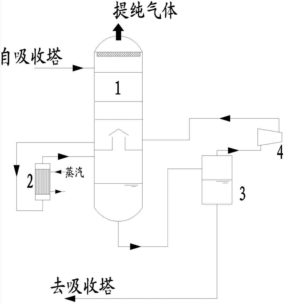
[0019] As shown in the accompanying drawings, a regeneration system of a flue gas carbon dioxide capture solution of the present invention includes a packed or plate distillation tower regeneration tower 1 connected to the absorption tower, and a vertical or vertical tower connected to the lower part of one side of the regeneration tower 1. Horizontal thermosyphon reboiler 2, reboiler 2 is provided with external steam as a heat source, and the pressure vessel connected to the bottom of regeneration tower 1 that can realize gas-liquid separation Gas-liquid separator 3, the bottom of gas-liquid separator 3 and the absorption tower The top is in communication with the air pump 4, the air pump 4 is a pump or turbine that can realize gas compression, and the air pump 4 is in communication with the lower part of the other side of the regenerati...


PUM


Abstract

The invention discloses a regeneration system for smoke carbon dioxide capture solution, comprising a regeneration tower, a reboiler and a gas-liquid separator, wherein the generation tower is communicated with an adsorption tower; the lower part of one side of the regeneration tower is communicated with the reboiler; the gas-liquid separator is communicated with the bottom of the regeneration tower; the bottom of the gas-liquid separator is communicated with the adsorption tower; the top of the gas-liquid separator is conducted with an air pump; and the lower parts of the other sides of the air pump and the regeneration tower are communicated. The regeneration system can be used for the fields of coal fired power plant boilers and chemical industry and is easier to release because of fully utilizing the residual heat of regeneration solution and utilizing the carbon dioxide under lower pressure, the desorption rate of the carbon dioxide is improved, the regeneration degree of the solution is improved, and the regeneration energy consumption for capturing the unit carbon dioxide is reduced.

Description

technical field [0001] The invention relates to the technical field of flue gas carbon dioxide capture, in particular to a regeneration system for a flue gas carbon dioxide capture solution. Background technique [0002] In recent years, the pressure of global warming on governments and energy companies has increased rapidly, and many western countries have begun to promote substantial decarbonization work. With my country's carbon emissions surpassing that of the United States and the international call for emission reductions, carbon dioxide capture in power plants is likely to become a technology that my country needs in the short and medium term. More than 3 / 4 of the existing power stations in my country are thermal power generation, and there is no IGCC power station in commercial operation. Therefore, it is the most urgent need to develop an alcohol amine absorption carbon capture technology suitable for traditional power plants. [0003] The technology of carbon dio...

Claims


Application Information

Patent Timeline
Patent Type & Authority Patents(China)
IPC IPC(8): B01D53/18C01B31/20C01B32/50
CPCY02P20/152Y02P20/151
Inventor 刘练波郜时旺许世森牛红伟蔡铭王金意缑志斌
Owner HUANENG CLEAN ENERGY RES INST
Learn More