Rod fin-type horizontal double-shaft stirring reboiler with propulsion blades

A propelling blade, horizontal double shaft technology, applied in mixers with rotary stirring devices, chemical instruments and methods, dissolution and other directions, can solve the problem of poor stirring effect of reboiler, poor heat transfer effect of reboiler, and product loss. It can ensure the safe and continuous operation, shorten the residence time, and reduce the thermal loss.

Inactive Publication Date: 2012-02-15
TIANJIN UNIV
View PDF4 Cites 5 Cited by
  • Summary
  • Abstract
  • Description
  • Claims
  • Application Information

AI Technical Summary

Problems solved by technology

For high-boiling point materials, especially heavy tar or phenol tar, coal tar, polymers and other similar materials with high viscosity, high freezing point, and strong heat sensitivity, they usually foam or expand at high temperatures. There may even be rheological solidification. If a conventional thermosiphon or Keitel reboiler is used, the viscosity of the material is high, the temperature is high, and the fluidity is poor, especially in the reboiler. Poor, there are many dead angles, some materials are easy to stay between the heat exchange tubes, and it is easy to cause carbonization or puffing (become solid after foaming), resulting in poor heat transfer effect, or even blockage of equipment, so that the operation cannot be carried out normally
If a conventional thermosiphon or Keitel reboiler is used, in order to ensure long-term safe operation, it must be ensured that the viscosity of the material in the reboiler is not too high and has a certain degree of fluidity,

Method used


Image

  • Rod fin-type horizontal double-shaft stirring reboiler with propulsion blades
  • Rod fin-type horizontal double-shaft stirring reboiler with propulsion blades
  • Rod fin-type horizontal double-shaft stirring reboiler with propulsion blades

Examples


Embodiment Construction

[0011] The present invention will be described in detail below in conjunction with the accompanying drawings and specific embodiments.

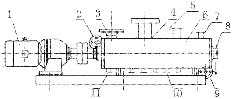
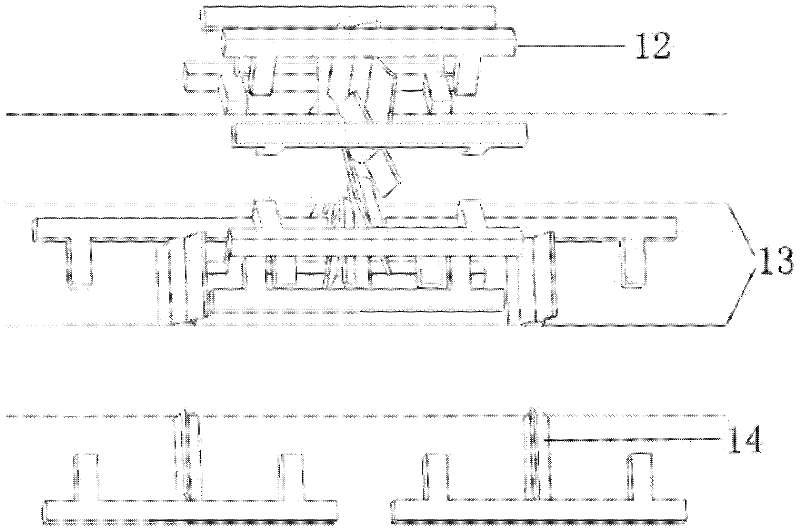
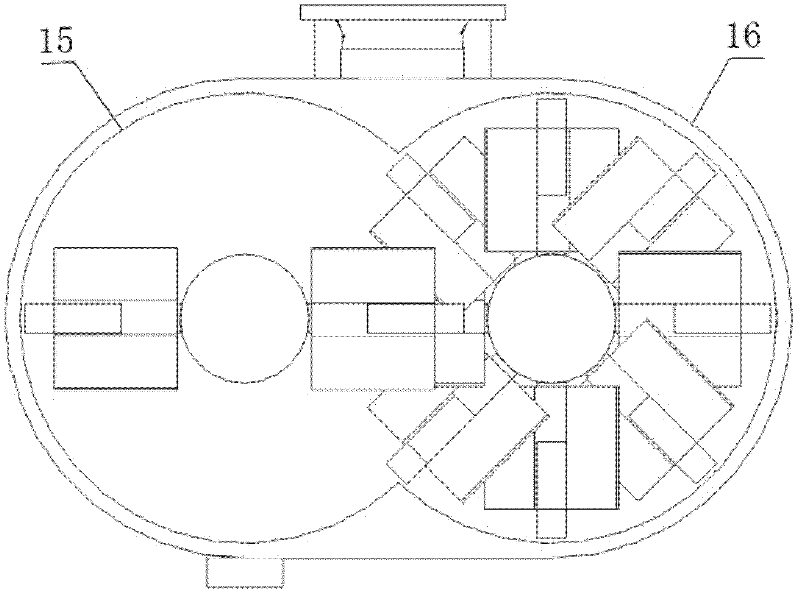
[0012] like figure 1 The shown rod-fin horizontal twin-shaft stirring reboiler with propulsion blades of the present invention includes a kettle body 6, a motor 1 and a speed reducer connected to the motor 1, and at the top of the kettle body A material inlet 3, a gas outlet 4 and a manhole 5 are respectively provided, and a plurality of material outlets 8 and 10 are arranged on the bottom or the side wall of the kettle body 6, and the described speed reducer is arranged in the kettle body 6 The two rotating shafts 13 connected to the output shaft are respectively provided with a plurality of rod-type stirring fins 12 at intervals on the two rotating shafts, and each rod-type stirring fin 12 is provided with a propulsion blade 14 . The rod-type stirring fins and propulsion blades on the two rotating shafts are arranged alternately. The cent...


PUM


Abstract

The invention discloses a rod fin-type horizontal double-shaft stirring reboiler with propulsion blades. The rod fin-type horizontal double-shaft stirring reboiler with propulsion blades comprises a kettle body, a motor and a speed reducer connected to the motor. The top of the kettle body is provided respectively with a material inlet, a gas outlet and a manhole. Multiple material outlets are arranged at the bottom or a side wall of the kettle body. Two rotating shafts connected to an output shaft of the speed reducer are arranged in the kettle body. The two rotating shafts are respectively provided with multiple rod-type stirring fins at intervals. Each one of the rod-type stirring fins is provided with a propulsion blade. The rod-type stirring fins and the propulsion blades of the two rotating shafts are arranged crisscross. The rod fin-type horizontal double-shaft stirring reboiler with propulsion blades eliminates stirring blind angles and enhances stirring effects. Through the action between the rod-type stirring fins and the action between the rod-type stirring fins and the inner wall of the kettle body, materials bonded to the rod-type stirring fins and the inner wall of the kettle body can be scraped. Therefore, the rod fin-type horizontal double-shaft stirring reboiler with propulsion blades has strong self-cleaning effects and can avoid that materials are bonded to the interior of the kettle body.

Description

technical field [0001] The invention relates to a reboiler, in particular to a rod-fin horizontal double-shaft stirring reboiler with propulsion blades having strong stirring, heat transfer and mass transfer effects. Background technique [0002] Thermosiphon reboilers and Kettle kettle reboilers are often used in evaporation and distillation processes (ZL 200920088831.3, 2010; ZL 200810053594.7, 2010). The Kettle kettle reboiler is equipped with a gas outlet and a manhole on the top of the kettle body, and a material outlet at the bottom of the reboiler; the bottom of the reboiler of the thermosiphon reboiler is equipped with a material inlet and a gas outlet at the top. Part of the material is heated to the boiling state by the heat medium in the tube side in the evaporator, and then enters the distillation tower from the gas outlet. For high-boiling point materials, especially heavy tar or phenol tar, coal tar, polymers and other similar materials with high viscosity, hi...

Claims


Application Information

Patent Timeline
IPC IPC(8): B01F7/04
Inventor 冯惠生刘叶凤单纯徐菲菲杨腾
Owner TIANJIN UNIV
Why Eureka
Try Eureka