
Testing device for outlet logics of main transformer, differential bus device, and automatic bus transfer device

A logic test and bus difference technology, applied in the field of automatic control devices, can solve problems such as wasting a lot of time, potential safety hazards, and incorrect contact actions, and achieve the effects of improving work efficiency, avoiding missed tests, and reducing labor load

Active Publication Date: 2012-02-15
GUANGAN POWER SUPPLY COMPANY STATE GRID SICHUANELECTRIC POWER
View PDF6 Cites 10 Cited by
  • Summary
  • Abstract
  • Description
  • Claims
  • Application Information

AI Technical Summary

Problems solved by technology

For example, how high the backup protection is, generally through multiple experiments to test the bus connection, the local side and the jump circuit of the high backup, but there is no way to test whether other related circuits have false exits. If you want to test whether other contacts are The exit will repeatedly test the protection action back and forth, wasting a lot of time
During the test, the protection device will generally return to the whole group 3-5 seconds after the action. Sometimes the protection group does not know after the whole group is restored. The relay protection testers still test according to the protection action, which may cause the relay protection personnel to make false tests;
[0004] (2) For bus differential protection: relay protection personnel often use the multimeter test method to test the action exit logic of the protection, but the multimeter test method cannot test the action time of the bus differential protection, so it is impossible to judge whether the action exit time meets the requirements. A lot of time will be wasted if each loop test is required;
[0005] (3) For standby automatic switching: the existing relay protection tester cannot test the time and exit logic of the complete action process of standby automatic switching. Usually, the standby automatic switching is tested in sections, and then the exit time and logic are tested step by step. In this way, the contact action that may be tested is incorrect.
[0006] During the first inspection of new substations and substations, it is required to fully inspect the action logic and time of protection. However, the current power system has put forward very high requirements for the duration of protection inspections. If the test is carried out according to the traditional method, not only may there be certain safety Hidden dangers, and may cause many projects not to be completed on schedule

Method used


Image

  • Testing device for outlet logics of main transformer, differential bus device, and automatic bus transfer device
  • Testing device for outlet logics of main transformer, differential bus device, and automatic bus transfer device

Examples


Embodiment Construction

[0015] In order to make the object, technical solution and advantages of the present invention more clear, the present invention will be further described in detail below in conjunction with the accompanying drawings and embodiments. It should be understood that the specific embodiments described here are only used to explain the present invention, not to limit the present invention.

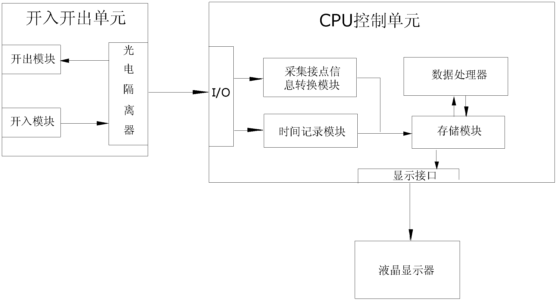
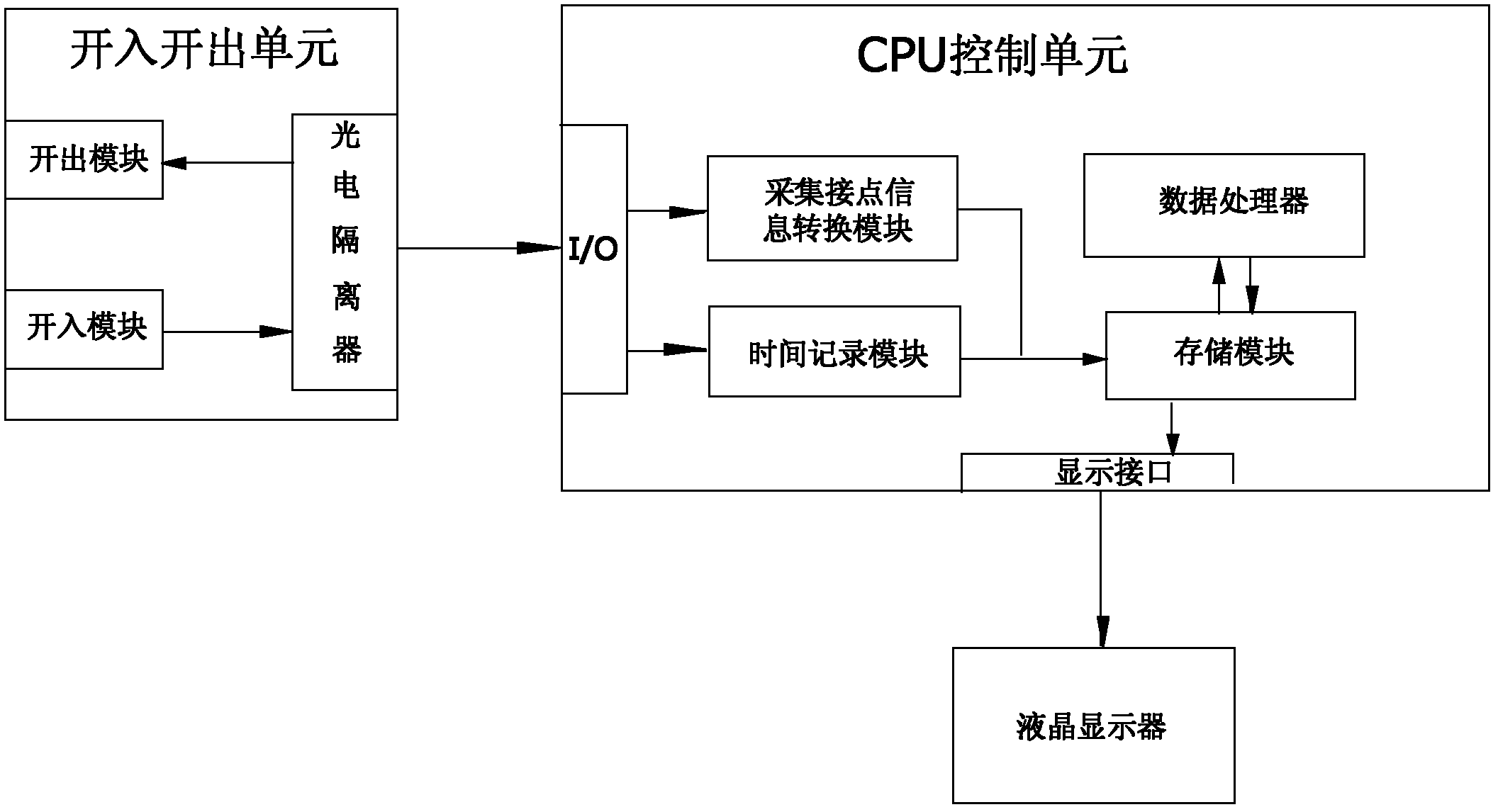
[0016] As shown in the accompanying drawings, the present invention includes a binary input and output unit, a CPU control unit and a liquid crystal display. The contact is connected with the digital input terminal of the relay protection tester, which is used to start the relay protection tester to output the fault value when the key is activated. The signal input terminal of the output module is connected with the photoelectric isolator, and the input module is provided with a contact with the acquisition The connected interface, and the digital input terminal connected to the digital output c...


PUM


Abstract

The invention discloses a testing device for outlet logics of a main transformer, a differential bus device, and an automatic bus transfer device. The testing device comprises an input and output unit, a CPU control unit and a liquid crystal display. The input and output unit includes an input module, an output module and a photoisolator. A switching value output contact of the output module is connected with a switching value input terminal of a relay protection tester; and a signal input terminal of the output module is connected with the photoisolator. 16 to 24 pairs of interfaces that are connected with collection contacts, a switching value input terminal that is connected with a switching value output contact of the relay protection tester and a switching value input terminal that is connected with an output contact of a trigger button are arranged on the input module; and a signal output terminal of the input module is connected with the photoisolator. And the CPU control unit consists of a collection contact information conversion module, a time recording module, a storage module and a data processor. According to the invention, pulses of all outlet press plates can be tested on the condition that protection only makes one-time motion.

Description

technical field [0001] The invention relates to an automatic control device for testing the displacement of an outlet contact of a relay protection of a power system, in particular to a logic test device for a main transformer, a bus differential, and a backup direct input outlet. Background technique [0002] At present, the conventional relay protection tester has not made a breakthrough in testing the logic and action time of multiple protection contacts. Usually, the test pulse of a relatively primitive multimeter or the action time of a single outlet contact is tested by a relay protection tester. Since various types of protection devices generally reset the entire group within 3-5 seconds after they operate, protection personnel have to add fault data again to test the operation time of other contacts, so as to judge the operation logic. For devices such as main transformers, bus differentials, and backup self-injections that involve many outlet contact circuits and co...

Claims


Application Information

Patent Timeline
Patent Type & Authority Applications(China)
IPC IPC(8): G01R31/00G01R31/327
Inventor 余嘉庆许梅周劲李群军
Owner GUANGAN POWER SUPPLY COMPANY STATE GRID SICHUANELECTRIC POWER
Learn More