Semiconductor side pumped solid-state laser
A solid-state laser, side-pumped technology, applied in lasers, laser parts, phonon exciters, etc., can solve problems such as unfavorable laser processing, large diffraction loss and geometric loss, and irreversible changes in the optical path.
- Summary
- Abstract
- Description
- Claims
- Application Information
AI Technical Summary
Problems solved by technology
Method used
Image
Examples
Embodiment approach 1
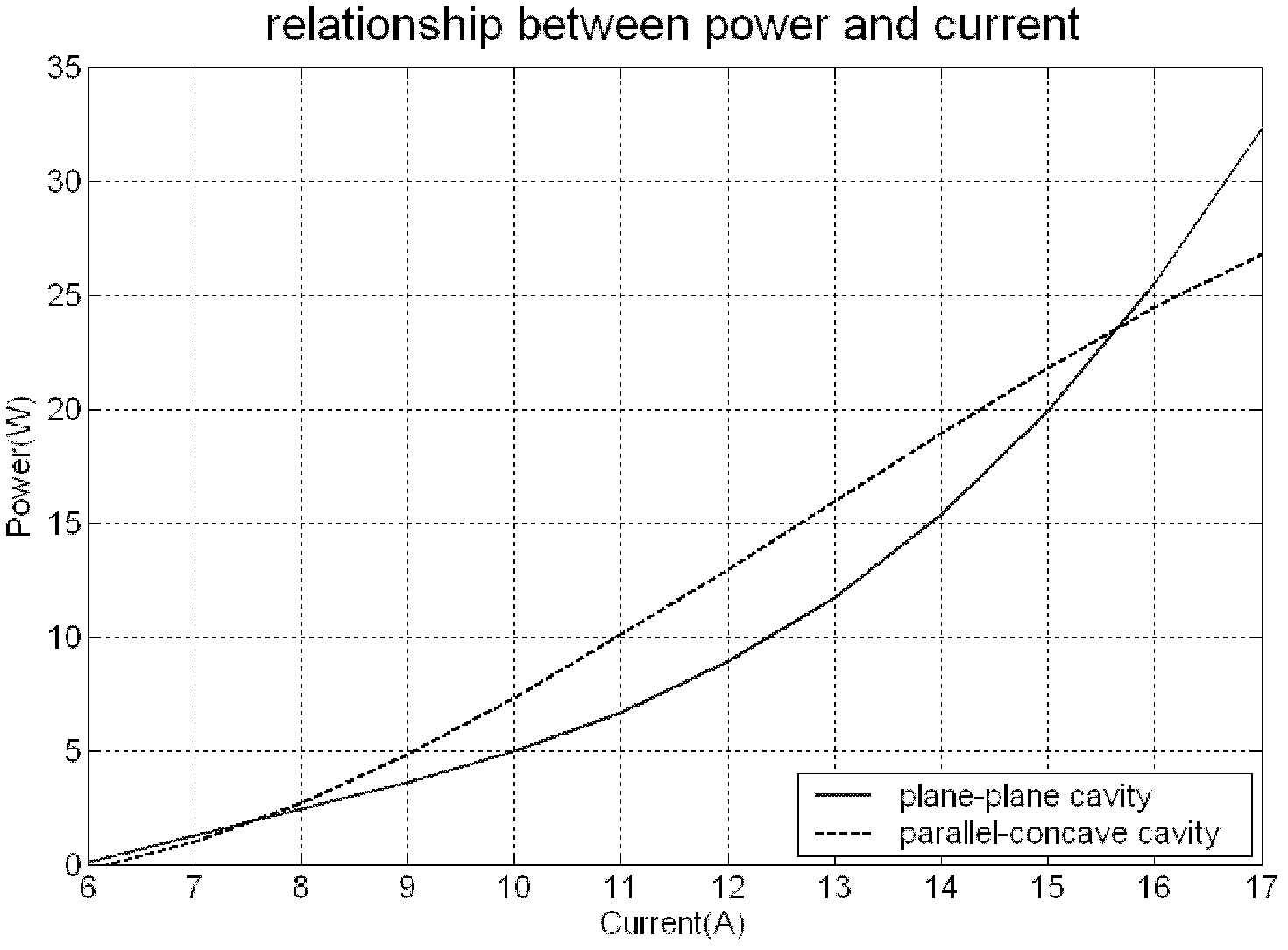
[0026] figure 1 It is a schematic diagram of the physical structure of a 1064nm semiconductor side-pumped solid-state laser, and its corresponding optical path structure diagram is as follows figure 2 As shown, the semiconductor side-pumped solid-state laser includes a laser module, a resonant cavity, and a cooling system. The laser module 5 uses a 50W laser module from Haite Optoelectronics. The resonant cavity includes a total reflection mirror 2, an output mirror 6, and an aperture diaphragm. 3. The total reflection mirror 2 and the output mirror 6 are plano-concave mirrors with a certain radius of curvature, and an aperture stop 3 is placed near the total reflection mirror in the cavity. The beam expander 7 is arranged on the output optical path of the output mirror 6 . In addition, 1 in the figure is a red light indicator, and 7 is a beam expander (optional). The function of the red light indicator 1 is: to align the optical path during dimming; to indicate the position...
Embodiment approach 2
[0034] Using the structure of Embodiment 1, the total reflection mirror 2 is replaced by the radius of curvature R 1 =4m plano-concave mirror, coated with 1064nm HR film on the concave surface, HR film reflectivity R>99.8%; output mirror 6 is replaced by curvature radius R 2 =0.6m plano-concave mirror, coated with 1064nm transmittance T=25% film on the concave surface, coated with 1064nm AR film on the plane, AR film reflectivity R<0.2%. The distance between the output mirror 6 and the total reflection mirror 2 is changed to 0.3m, and the distance between the aperture diaphragm 3 and the total reflection mirror 2 is adjusted to 0.06m.
[0035] Using this structure, the maximum continuous output power of 33W can be obtained, the power instability is less than 2% within four hours, the beam quality is lower than that of Embodiment 1, the far-field divergence angle is enlarged, and the spot size is 2.8mm.
Embodiment approach 3
[0037] Using the structure of Embodiment 1, the total reflection mirror 2 is replaced by the radius of curvature R 1 =6m plano-concave mirror, coated with 1064nm HR film on the concave surface, HR film reflectivity R>99.8%; output mirror 6 is replaced by curvature radius R 2 =0.8m plano-concave mirror, coated with 1064nm transmittance T=25% film on the concave surface, coated with 1064nm AR film on the plane, AR film reflectivity R<0.2%. The distance between the output mirror 6 and the total reflection mirror 2 is changed to 0.5m, and the distance between the aperture diaphragm 3 and the total reflection mirror 2 is adjusted to 0.08m.
[0038] Using this structure, the maximum continuous output power of 30W can be obtained, the power instability is less than 3% within four hours, the beam quality is lower than that of Embodiment 1, the far-field divergence angle is reduced, and the spot size is 3.2mm.
PUM
 Abstract
Description
Claims
Application Information
 - R&D
- Intellectual Property
- Life Sciences
- Materials
- Tech Scout
- Unparalleled Data Quality
- Higher Quality Content
- 60% Fewer Hallucinations
Browse by: Latest US Patents, China's latest patents, Technical Efficacy Thesaurus, Application Domain, Technology Topic, Popular Technical Reports.
© 2025 PatSnap. All rights reserved.Legal|Privacy policy|Modern Slavery Act Transparency Statement|Sitemap|About US| Contact US: help@patsnap.com


