Kitchen waste crushing and squeezing processor

A kitchen waste and processing machine technology, applied in the direction of presses, grain processing, manufacturing tools, etc., to achieve good crushing effect, improve waste processing efficiency, and speed up.

Active Publication Date: 2012-02-22
邢征
View PDF12 Cites 28 Cited by
  • Summary
  • Abstract
  • Description
  • Claims
  • Application Information

AI Technical Summary

Problems solved by technology

[0004] In order to solve the defect that there is no special kitchen waste treatment equipment in the prior art, the present invention provides a kitchen waste crushing and pressing machine

Method used


Image

  • Kitchen waste crushing and squeezing processor
  • Kitchen waste crushing and squeezing processor
  • Kitchen waste crushing and squeezing processor

Examples


Embodiment 1

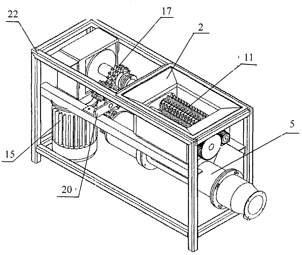
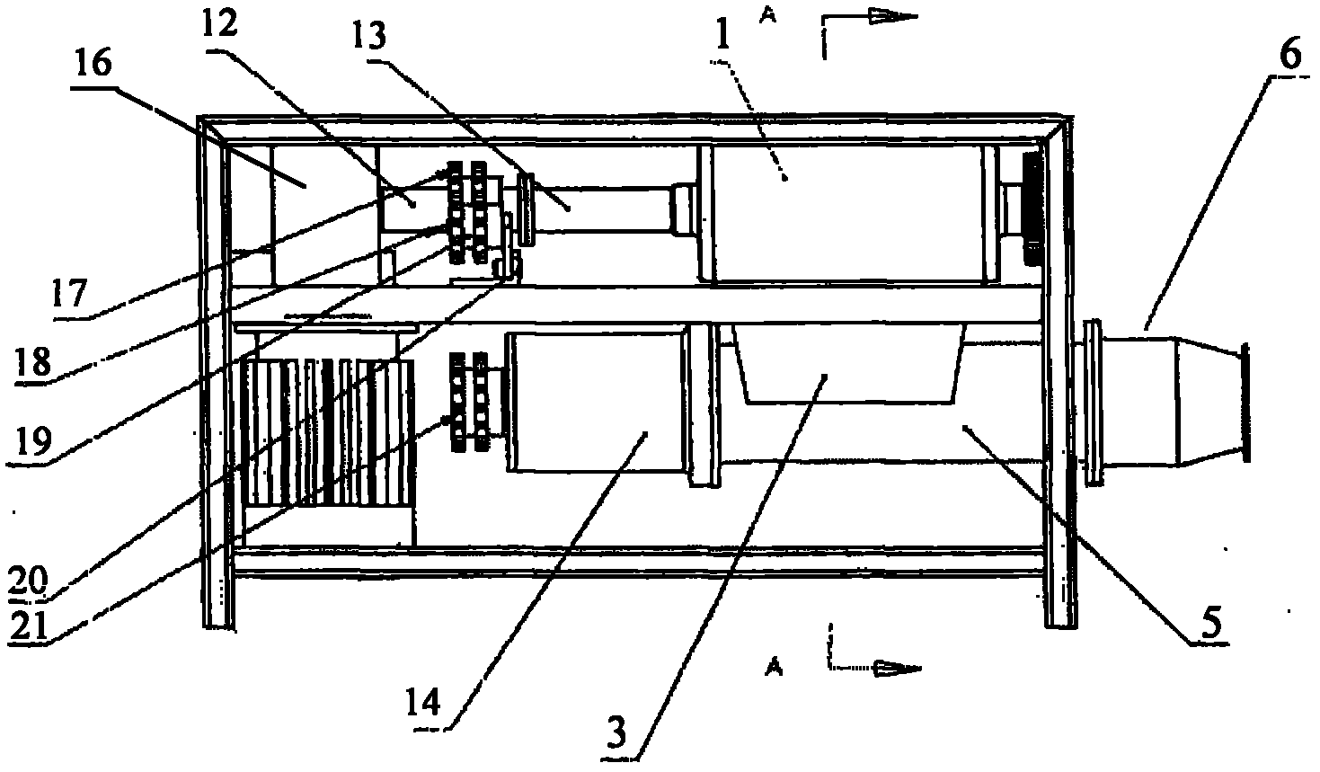
[0064] Such as Figure 1 to Figure 16 As shown, the kitchen waste crushing and pressing machine provided by the present invention includes a power part, a supporting part, a power transmission part, a crushing part, and a pressing and dehydrating part; the power part includes a motor 15, and the supporting part includes a support plate 20 and a frame 22. The power transmission part includes a reducer 16, a connector 12 and a connector 13, a shaft body 14, a sprocket 17, a sprocket 19, a sprocket 21 and a chain, and the crushing part includes a crushing box 1, and the upper end of the crushing box 1 is provided with a feed Port 2, the crushing box 1 is equipped with a roller-type crushing mechanism, and the lower end of the crushing box 1 is provided with a material channel 3; Figure 13 to Figure 16 As shown, the press dehydration part includes a screw 4, a storage sleeve 5, a screen 23 and a press sleeve 6, the screw 4 is installed in the storage sleeve 5, and the upper wall ...

Embodiment 2

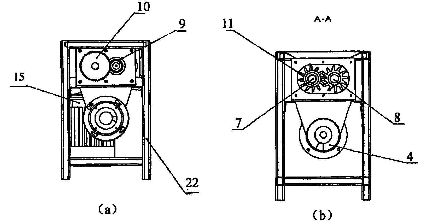
[0078] The apex angle of the shaft section at one end of the conical shape of the screw rod 4 is 80°, as Figure 6 and Figure 8 As shown, the top of the gear tooth 26 of the gear 11 is a sharp edge-shaped tooth tip 27 formed by a slope and a vertical surface perpendicular to the base circle of the tooth root, and the angle between the slope and the vertical surface is 30°. Such as Figure 9 and Figure 10 As shown, the gap L between the gear teeth 26 and the washer 11 is 0.2mm, as Figure 12 As shown, the gap S between the gear teeth 261 on the driving shaft 7 and the adjacent gear teeth 262 on the driven shaft 8 is 0.2mm, as Figure 15 (a) and Figure 15 As shown in (c), the shape of the taper cylinder 602 is a truncated cone, and the angle a between the two generatrices of the axial section of the truncated cone is 20°.

[0079] Other specific implementations are the same as in Example 1.

Embodiment 3

[0081] The apex angle of the axial section of the conical one end of the screw rod 4 is 110°, as Figure 6 and Figure 8 As shown, the top of the gear tooth 26 of the gear 11 is a sharp edge-shaped tooth tip 27 formed by a slope and a vertical surface perpendicular to the base circle of the tooth root, and the angle between the slope and the vertical surface is 70°. Such as Figure 9 and Figure 10 As shown, the gap L between the gear teeth 26 and the washer 11 is 1mm, as Figure 12 As shown, the gap S between the gear teeth 261 on the driving shaft 7 and the adjacent gear teeth 262 on the driven shaft 8 is 1mm, as Figure 15 (a) and Figure 15 As shown in (c), the shape of the tapered cylinder 602 is a truncated cone, and the angle a between the two generatrices of the axial section of the truncated cone is 40°.

[0082] Other specific implementations are the same as in Example 1.


PUM


Abstract

The invention belongs to the field of environmental protection, and relates to a waste processing device, in particular to a kitchen waste crushing and squeezing processor. In order to overcome the defect of the lack of special kitchen waste processing equipment in the prior art, the invention provides a kitchen waste crushing and squeezing processor. The kitchen waste crushing and squeezing processor comprises a crushing part and a squeezing and dewatering part, wherein the crushing part comprises a roll type crushing mechanism, the roll type crushing mechanism comprises a driving shaft and a driven shaft, gears are arranged on the driving shaft and the driven shaft respectively, each gear comprises a gear ring and a gasket, gear teeth are arranged on the gear ring, the cutting gap between tooth surfaces of adjacent gears is 0.5mm, and the cutting gap between tip-shaped tops of the gear teeth and the gaskets is 0.5mm. The kitchen waste crushing and squeezing processor integrates crushing, squeezing and dewatering, and can be used for efficiently processing kitchen waste.

Description

technical field [0001] The invention belongs to the field of environmental protection, and relates to a garbage treatment device, in particular to a kitchen waste crushing and pressing machine. Background technique [0002] With the continuous development of the economy, people's living standards are getting higher and higher, and there are more and more domestic garbage, among which kitchen waste (also known as kitchen waste) occupies a large proportion in the garbage. The main characteristics of kitchen waste are rich in organic matter, high in water content, and perishable. Its properties and odor will have a bad impact on environmental sanitation, and it is easy to breed harmful substances such as pathogenic microorganisms and mycotoxins. If it is not handled properly, it will bring people Extremely serious danger. On the other hand, nutrient-rich food waste is also a valuable renewable resource. Food waste that has been properly treated can be reused. [0003] At pre...

Claims


Application Information

Patent Timeline
Patent Type & Authority Applications(China)
IPC IPC(8): B09B3/00B02C4/08B02C4/42B02C4/30B30B9/14B30B15/00
Inventor 邢征
Owner 邢征
Why Eureka
Try Eureka