Kitchen waste crushing and squeezing processor
A kitchen waste and processing machine technology, applied in the direction of presses, grain processing, manufacturing tools, etc., to achieve the effect of reducing occupied space, reducing costs, and speeding up
- Summary
- Abstract
- Description
- Claims
- Application Information
AI Technical Summary
Problems solved by technology
Method used
Image
Examples
Embodiment 1
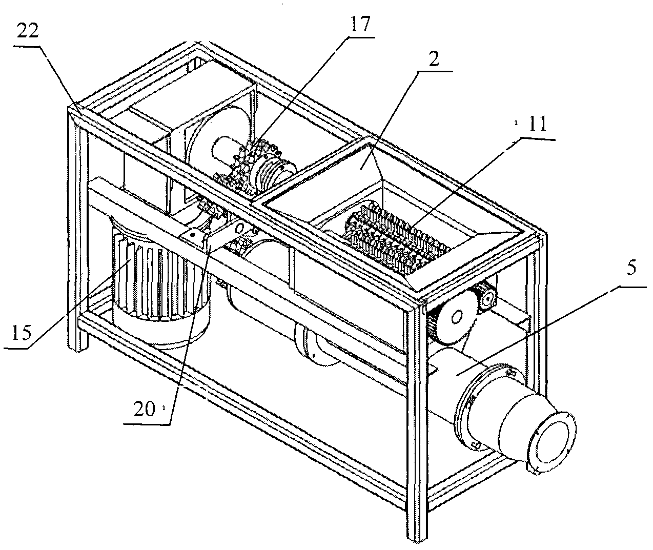
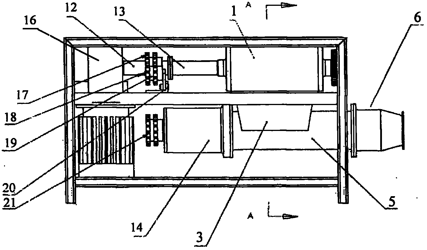
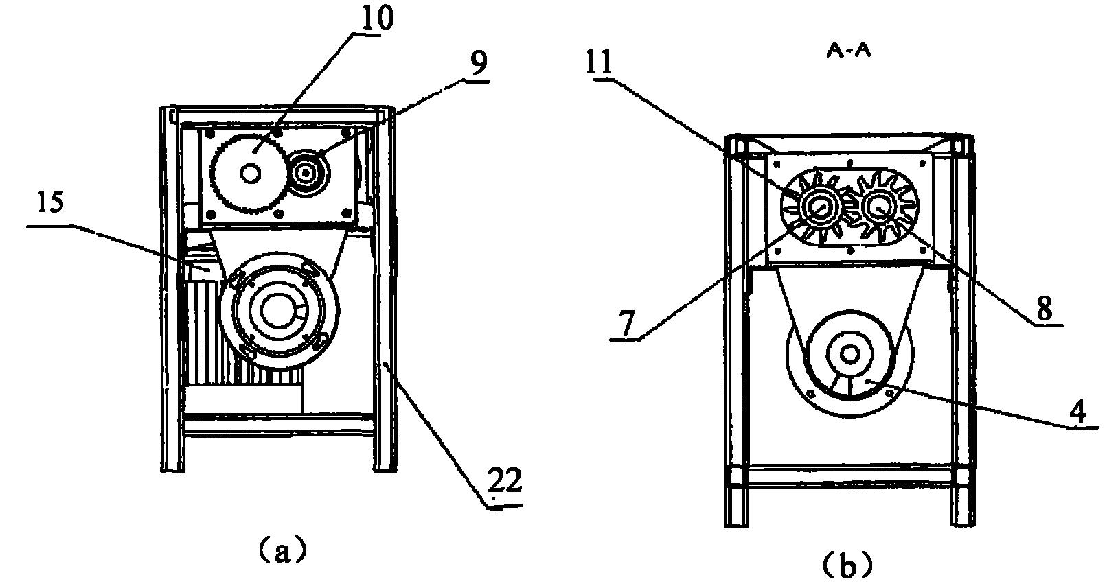
[0066] Such as Figure 1 to Figure 16 As shown, the kitchen waste crushing and pressing machine provided by the present invention includes a power part, a supporting part, a power transmission part, a crushing part, and a pressing and dehydrating part; the power part includes a motor 15, and the supporting part includes a support plate 20 and a frame 22. The power transmission part includes a reducer 16, a connector 12 and a connector 13, a shaft body 14, a sprocket 17, a sprocket 19, a sprocket 21 and a chain, and the crushing part includes a crushing box 1, and the upper end of the crushing box 1 is provided with a feed Port 2, the crushing box 1 is equipped with a roller-type crushing mechanism, and the lower end of the crushing box 1 is provided with a material channel 3; Figure 13 to Figure 16 As shown, the press dehydration part includes a screw 4, a storage sleeve 5, a screen 23 and a press sleeve 6, the screw 4 is installed in the storage sleeve 5, and the upper wall ...
Embodiment 2
[0080] The apex angle of the shaft section at one end of the conical shape of the screw rod 4 is 80°, as Figure 6 and Figure 8 As shown, the top of the gear tooth 26 of the gear 11 is a sharp edge-shaped tooth tip 27 formed by a slope and a vertical surface perpendicular to the base circle of the tooth root, and the angle between the slope and the vertical surface is 30°. Such as Figure 9 and Figure 10 As shown, the gap L between the gear teeth 26 and the washer 11 is 0.2mm, as Figure 12 As shown, the gap S between the gear teeth 261 on the driving shaft 7 and the adjacent gear teeth 262 on the driven shaft 8 is 0.2mm, as Figure 15 (a) and Figure 15 As shown in (c), the shape of the taper cylinder 602 is a truncated cone, and the angle a between the two generatrices of the axial section of the truncated cone is 20°.
[0081] Other specific implementations are the same as in Example 1.
Embodiment 3
[0083] The apex angle of the axial section of the conical one end of the screw rod 4 is 110°, as Figure 6 and Figure 8 As shown, the top of the gear tooth 26 of the gear 11 is a sharp edge-shaped tooth tip 27 formed by a slope and a vertical surface perpendicular to the base circle of the tooth root, and the angle between the slope and the vertical surface is 70°. Such as Figure 9 and Figure 10 As shown, the gap L between the gear teeth 26 and the washer 11 is 1mm, as Figure 12 As shown, the gap S between the gear teeth 261 on the driving shaft 7 and the adjacent gear teeth 262 on the driven shaft 8 is 1mm, as Figure 15 (a) and Figure 15 As shown in (c), the shape of the taper cylinder 602 is a truncated cone, and the angle a between the two generatrices of the axial section of the truncated cone is 40°.
[0084] Other specific implementations are the same as in Example 1.
PUM
 Abstract
Description
Claims
Application Information
 - R&D
- Intellectual Property
- Life Sciences
- Materials
- Tech Scout
- Unparalleled Data Quality
- Higher Quality Content
- 60% Fewer Hallucinations
Browse by: Latest US Patents, China's latest patents, Technical Efficacy Thesaurus, Application Domain, Technology Topic, Popular Technical Reports.
© 2025 PatSnap. All rights reserved.Legal|Privacy policy|Modern Slavery Act Transparency Statement|Sitemap|About US| Contact US: help@patsnap.com


