Aerodynamic high-performance aerofoil for aircraft

An aerodynamic and high-performance technology, applied in the field of aircraft airfoils, can solve the problems of difficult application and immature application of flow control technology, and achieve the effects of high safety, light weight and easy control

Inactive Publication Date: 2012-02-22
XI AN JIAOTONG UNIV
View PDF3 Cites 15 Cited by
  • Summary
  • Abstract
  • Description
  • Claims
  • Application Information

AI Technical Summary

Problems solved by technology

In the experiment, the flap vibration has a higher frequency, so it is also difficult to apply
Therefore,

Method used


Image

  • Aerodynamic high-performance aerofoil for aircraft
  • Aerodynamic high-performance aerofoil for aircraft
  • Aerodynamic high-performance aerofoil for aircraft

Examples


Embodiment 1

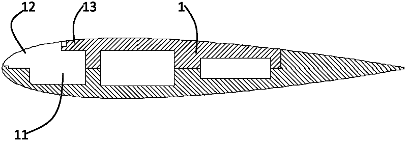
[0023] see figure 1 , the aerodynamic high-performance airfoil 1 used for the aircraft in this embodiment selects the NACA0015 airfoil. The chord length of the airfoil 1 is 800mm, and the spanwise width of the experimental part is 200mm. The airfoil 1 has a cavity 11 at the leading edge 2.2 mm to 126.4 mm, and an elastic structure 12 covering the cavity 11 . The elastic structure 12 is an elastic skin 12 . The cavity 11 is provided with an opening on the suction surface 13 of the airfoil 1 , the elastic skin 12 covers the surface of the opening, and the periphery of the elastic skin 12 is fixed on the airfoil 1 . In the specific implementation process, the elastic skin 12 is on the suction surface 13 of the airfoil 1. Since the elastic skin 12 is a flexible material, it has a strong fluid-solid coupling with the incoming flow. On the one hand, the elastic skin 12 Deformation will occur under load, on the other hand, the deformation of the elastic skin 12 will in turn affect...

Embodiment 2

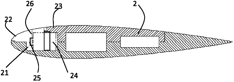
[0025] see figure 2 , the aerodynamic high-performance airfoil 2 used for the aircraft in this embodiment also selects the NACA0015 airfoil. The airfoil 2 has a cavity 21 at its leading edge 2.2 mm to 126.4 mm, and an elastic structure 22 covering the cavity 21 . The elastic structure 22 is an elastic skin 22 . The cavity 21 has an opening on the suction surface 23 of the airfoil 2 , the elastic skin 22 covers the surface of the opening, and the surrounding of the elastic skin 22 is fixed on the airfoil 2 . The airfoil 2 is also provided with an exciter 24 , a fixing device 25 and a spring 26 accommodated in the cavity 21 . The vibration amplitude of the vibrator 24 is 5 mm, and the vibration frequency can vary from 0 Hz to 200 Hz. One end of the spring 26 is connected to the exciter 24 by a fixing device 25 , and the other end of the spring 26 is fixed at the center of the elastic skin 22 . In this embodiment, the vibrator 24 is set at any excitation frequency between 0 ...

Embodiment 3

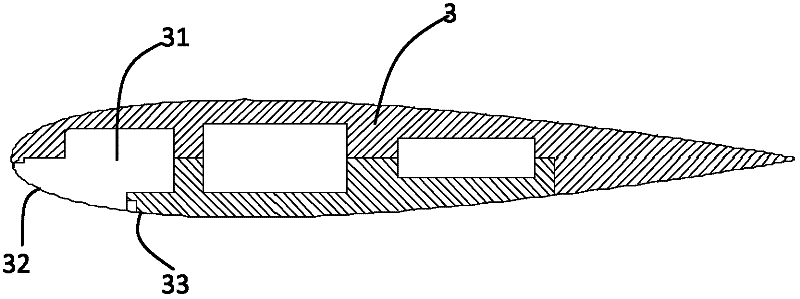
[0027] see image 3, the aerodynamic high-performance airfoil 3 used for aircraft in this embodiment is provided with a cavity 31 and an elastic skin 32, which are basically the same structure as in Embodiment 1. The difference is that the cavity 31 is provided with an opening on the pressure surface 33 of the airfoil 3 , and the elastic skin 32 covers the surface of the opening.


PUM


Abstract

The invention relates to an aerodynamic high-performance aerofoil for an aircraft. A leading edge of the aerodynamic high-performance aerofoil is provided with a cavity and an elastic skin covering an opening of the cavity. Through forced vibration loaded on an elastic structure or self-excited vibration produced by strong fluid-structure interaction with fluid in the flight, the aerodynamic high-performance aerofoil can control flow thereby improving aircraft aerodynamic performances. The aerodynamic high-performance aerofoil has the advantages of obvious lift-rising and drag reduction effects, simple structure, small volume, light quality, convenience for control, and high safety. The aerodynamic high-performance aerofoil has a large real application value and provides novel thinking for aerofoil development.

Description

technical field [0001] The invention relates to an aircraft airfoil, in particular to an aerodynamic high-performance airfoil structure for an aircraft. Background technique [0002] In the history of more than 100 years of aircraft development, how to make the aircraft obtain higher aerodynamic performance has always been the key goal pursued by various research institutes. In the early days of aircraft development, the famous aerodynamicist Prandtl first proposed the important concept of controlling the flow to improve the aerodynamic performance of the aircraft. At the time, this technique of controlling flow was proposed in the form of boundary layer control. In practical applications, the control of the boundary layer by blowing air tangentially to the surface has achieved great success. However, the traditional boundary layer control has problems such as complex technology and excessive additional mass produced by the pipeline system, which restricts its application....

Claims


Application Information

Patent Timeline
IPC IPC(8): B64C3/14B64C3/36
Inventor 张家忠陈嘉辉孙旭梅冠华
Owner XI AN JIAOTONG UNIV
Why Eureka
Try Eureka