Surface treatment technique of flow control valve

A flow control valve and surface treatment technology, applied in the field of processing technology, can solve problems such as increased leakage, increased fit gap between the flow control valve and the pump body, and affecting the performance of the steering pump of the automobile, so as to reduce the friction force and use The effect of life extension

Inactive Publication Date: 2012-02-22
NINGBO HONGBO MACHINERY MFG
View PDF2 Cites 2 Cited by
  • Summary
  • Abstract
  • Description
  • Claims
  • Application Information

AI Technical Summary

Problems solved by technology

[0003] The existing flow control valve was subjected to an impact test of 500,000 times on the durability test bench, the maximum pressure was 12Mpa, the impact frequency was 1HZ, and the oil temperature was 120°C. After the test was completed, the machine was disassembled for inspection. After testing: the flow rate The reduction of the outer circle of the control valve is 0.0043mm, and the increase of the hole in the pump body is 0.0067mm. Such wear and tear caused the increase of the fit clearance between the flow control valve and the pump body, and the increase of the leakage of the pump, which seriously affected the steering of the car. pump performance

Method used


Image

  • Surface treatment technique of flow control valve
  • Surface treatment technique of flow control valve

Examples


Embodiment 1

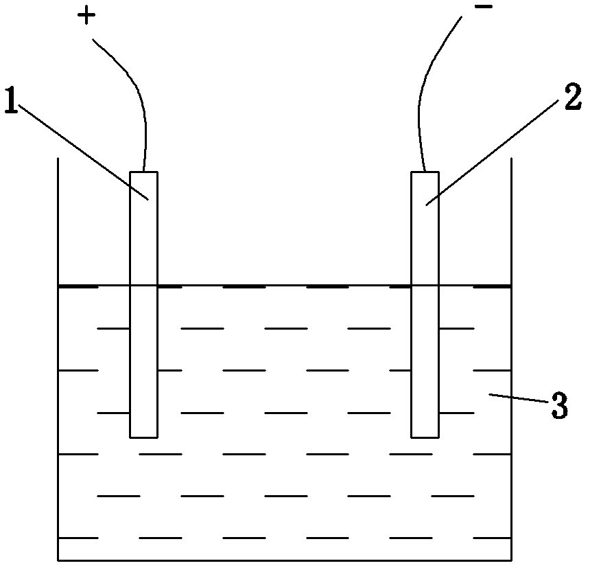
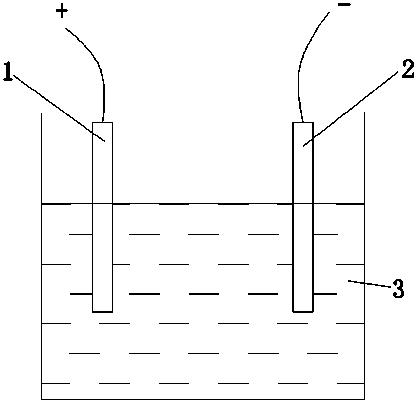
[0013] Such as figure 1 As shown, the flow control valve surface treatment process of the present invention, wherein the material used for the flow control valve is aluminum 6061, the flow control valve is used as the anode 1 and the lead plate is used as the cathode 2 during the treatment process, and the anode 1 and the cathode 2 are placed in the oxidizing solution In 3, the oxidation solution 3 is a mixed solution of 2.24mol / L sulfuric acid aqueous solution and 224mol / L polytetrafluoroethylene aqueous dispersion in a volume ratio of 3:1, the temperature of the mixed solution is -3°C, and the area of ​​the cathode 2 is It is 10 times the area of ​​the anode 1, and the DC power supply is connected. The stable oxidation current density of the anode 1 is 2.5A / dm. During the oxidation process, the oxidation solution 3 is stirred with a magnetic bar to absorb the magnetic impurities in the oxidation solution. In 2.5 hours, in the oxidation solution 3, the size of the polytetrafl...

Embodiment 2

[0015] Such as figure 1 As shown, the flow control valve surface treatment process of the present invention, wherein the material used for the flow control valve is aluminum 6061, the flow control valve is used as the anode 1 and the stainless steel plate is used as the cathode 2 during the treatment process, and the anode 1 and the cathode 2 are placed in the oxidizing solution In 3, the oxidation solution 3 is a mixed solution of 2.24mol / L sulfuric acid aqueous solution and 224mol / L polytetrafluoroethylene aqueous dispersion in a volume ratio of 3:1, the temperature of the mixed solution is -4°C, and the area of ​​the cathode 2 is It is 10 times the area of ​​the anode 1, and the DC power supply is connected. The stable oxidation current density of the anode 1 is 2.5A / dm. During the oxidation process, the oxidation solution 3 is stirred with a magnetic bar to absorb the magnetic impurities in the oxidation solution. For 3 hours, in the oxidation solution 3, the size of the p...

Embodiment 3

[0017] Such as figure 1 As shown, the flow control valve surface treatment process of the present invention, wherein the material used for the flow control valve is aluminum 6061, the flow control valve is used as the anode 1 and the lead plate is used as the cathode 2 during the treatment process, and the anode 1 and the cathode 2 are placed in the oxidizing solution In 3, the oxidizing solution 3 is a mixed solution of 2.24mol / L sulfuric acid aqueous solution and 224mol / L polytetrafluoroethylene aqueous dispersion in a volume ratio of 3:1, the temperature of the mixed solution is -3.5°C, and the area of ​​the cathode 2 is It is 10 times the area of ​​the anode 1, and the DC power supply is connected. The stable oxidation current density of the anode 1 is 2.5A / dm. During the oxidation process, the oxidation solution 3 is stirred with a magnetic bar to absorb the magnetic impurities in the oxidation solution. In 2.7 hours, in the oxidation solution 3, the size of the polytetra...


PUM


Abstract

The invention relates to a surface treatment technique of a flow control valve, belonging to the technical field of metal surface treatment. In the treatment process, a flow control valve is used as an anode, and the anode and a cathode are arranged in an oxidant solution. The invention is characterized in that the oxidant solution is a mixed solution formed by mixing a 2.24 mol/L sulfuric acid water solution and a 224 mol/L polytetrafluoroethylene water dispersion in a volume ratio of 3:1, the temperature of the oxidant solution is -3--4 DEG C, the stable oxidation current density of the anode is 2.5 A/dm, the oxidation time is 2.5-3 hours, and a composite hard anodic oxidation layer is formed on the surface of the flow control valve. The flow control valve subjected to the surface treatment technique has the self-lubricating function, and can greatly reduce the friction force in the friction process with a pump body.

Description

technical field [0001] The invention relates to a treatment process, in particular to a metal surface treatment process. Background technique [0002] The flow control valve in the automobile steering pump is used after the surface is hard anodized with aluminum 6061. The material of the partner friction part, that is, the pump body is cast aluminum 109. During use, the pump body and the flow control valve have excessive Wear, especially after long-term use, this wear phenomenon is more serious. [0003] The existing flow control valve was subjected to an impact test of 500,000 times on the durability test bench, the maximum pressure was 12Mpa, the impact frequency was 1HZ, and the oil temperature was 120°C. After the test was completed, the machine was disassembled for inspection. After testing: flow The reduction of the outer circle of the control valve is 0.0043mm, and the increase of the hole in the pump body is 0.0067mm. Such wear causes the increase of the fit clearan...

Claims


Application Information

Patent Timeline
Patent Type & Authority Applications(China)
IPC IPC(8): C25D11/08
Inventor 何衍
Owner NINGBO HONGBO MACHINERY MFG
Why Eureka
Try Eureka