Fuel-gas-heating directional solidification furnace

A technology of directional solidification furnace and gas heating, which is applied in self-solidification, polycrystalline material growth, crystal growth, etc., can solve the problems of high operating cost and single selection of heat source, and meet the requirements of the process, save energy, and the heating process can be control effect

Inactive Publication Date: 2014-01-15
宁波国钰光伏材料有限公司
View PDF4 Cites 0 Cited by
  • Summary
  • Abstract
  • Description
  • Claims
  • Application Information

AI Technical Summary

Problems solved by technology

[0003] The purpose of the present invention is to solve the problem of single heat source selection and high operating cost in the existing directional solidification method, in order to increase the selection of diversified energy sources and reduce energy consumption costs, and provide a gas-heated directional solidification furnace with reasonable structural design. It mainly combines the good flame propagation and heat transfer performance of foam ceramics with the directional solidification furnace of quartz crucible, that is, the method of heating by induction coil or resistance is replaced by gas flame heating, so as to uniquely design the overall structure of the furnace body. To meet the technological requirements of metallurgical polysilicon directional solidification furnace

Method used


Image

  • Fuel-gas-heating directional solidification furnace
  • Fuel-gas-heating directional solidification furnace

Examples


Embodiment Construction

[0018] The technical solutions of the present invention will be further specifically described below through the embodiments and in conjunction with the accompanying drawings.

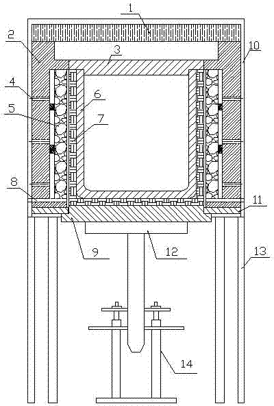
[0019] see figure 1 , a gas-fired heating directional solidification furnace in this embodiment, a supporting steel base 13 is provided, a lifting mechanism 14 is provided at the middle of the bottom of the supporting steel base 13, and the furnace body is above the supporting steel base 13.

[0020] The core of the heating zone in the furnace body is a square quartz crucible 6, and the crucible 6 is covered with a crucible protective cover 7 made of mullite material. The top of the crucible 6 is provided with a crucible cover 3 of quartz material having the same shape as the opening of the crucible 6 .

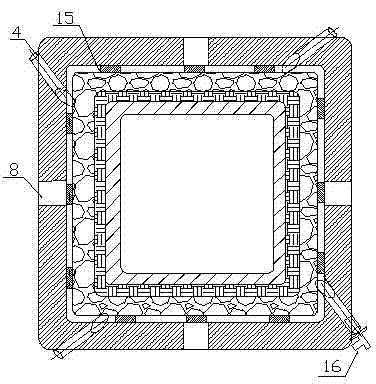
[0021] The ceramic foam layer 5 is arranged along the outer four sides of the crucible protective layer 7, and side wall positioning bricks 15 are installed between the furnace wall 2 and the ceramic...


PUM


Abstract

The invention relates to a directional solidification technology, in particular to a fuel-gas-heating directional solidification furnace used in a metallurgical-process polycrystalline silicon preparation process and aiming to solve the problems of singleness in selecting heat sources and higher operating cost of the traditional directional solidification method. The directional solidification furnace disclosed by the invention comprises a supporting steel base, a lifting mechanism arranged at a middle position of the bottom of the supporting steel base, and a furnace body fixed on the supporting steel base. The directional solidification furnace is characterized in that a supporting platform is arranged above the lifting mechanism, a crucible is arranged above the supporting platform and is located at a core part of the furnace body, the furnace body comprises a shell, a furnace wall is arranged at the inner side of the shell, a foamed ceramic layer is arranged at the inner side of the furnace wall, a crucible protecting layer is arranged at the inner side of the foamed ceramic layer, the crucible protecting layer is appressed to the crucible, a burner nozzle channel is formed in the furnace wall, a gap is formed between the furnace wall and the foamed ceramic layer, a plurality of heating areas are divided into along the up-down direction of the crucible, and each heating area is provided with a plurality of burner nozzles. According to the invention, fuel gas energy can be adopted to replace electric energy, and the advantages of controllable heating process, energy saving and low manufacturing cost are achieved.

Description

technical field [0001] The invention relates to directional solidification technology, in particular to a gas-heated directional solidification furnace in the process of preparing polysilicon by metallurgy. Background technique [0002] Directional solidification technology is widely used in industry, mainly used to produce magnetic materials, aviation and ground gas turbine blades, self-generated composite materials and various functional crystals; in the field of research, directional solidification is the basic means to study metal solidification and crystal growth . The directional solidification method usually refers to the method of melting in the same crucible, using impurity elements in the solid phase and liquid phase, and the segregation effect to achieve the purpose of purification. At the same time, the melt in the crucible reaches a certain temperature through unidirectional heat flow control. Gradient, so as to obtain the columnar grain structure neatly arrang...

Claims


Application Information

Patent Timeline
Patent Type & Authority Patents(China)
IPC IPC(8): C30B28/06C30B11/00B22D27/04
Inventor 方来仁方立峰杜少峰王子延刘小稚
Owner 宁波国钰光伏材料有限公司
Why Eureka
Try Eureka