Laser range finder and working method thereof

A technology of laser range finder and laser head, which is applied in the field of laser range finder, can solve problems such as dust content error, achieve accurate measurement and improve the effect of measurement accuracy

Inactive Publication Date: 2012-02-22
UNIV OF SHANGHAI FOR SCI & TECH
View PDF6 Cites 29 Cited by
  • Summary
  • Abstract
  • Description
  • Claims
  • Application Information

AI Technical Summary

Problems solved by technology

Due to climate change, changes in air humidit

Method used


Image

  • Laser range finder and working method thereof
  • Laser range finder and working method thereof
  • Laser range finder and working method thereof

Examples


Embodiment Construction

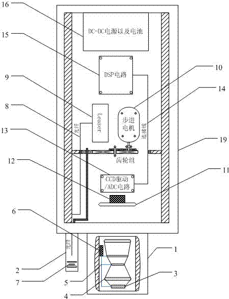
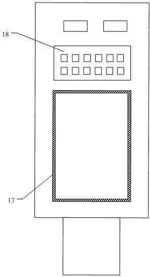
[0024] Such as figure 1 Shown is a schematic cross-sectional structure diagram of the laser rangefinder, showing its internal structure and layout. figure 2 It is a top view of the laser rangefinder, showing its external structure, liquid crystal for display and buttons for controlling measurement.

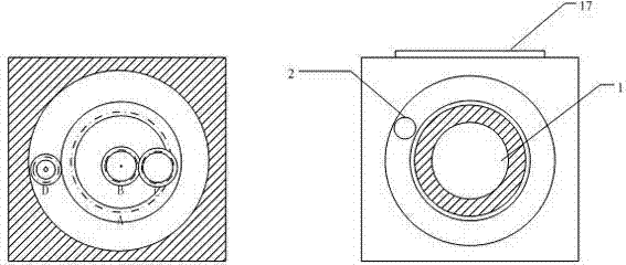
[0025] Such as figure 1 and 2 The structure diagram of the laser tester is shown. The entire laser rangefinder includes an optical system, a hardware circuit system, a mechanical system as a casing, and an image processing and measurement software part. The optical system is composed of a lens 1 and a rotatable laser head 2. The hardware circuit system consists of Area array CCD image sensor 11, image acquisition and processing circuit, drive module of rotatable laser head 2, power supply module 16, liquid crystal 17 for displaying information and keys 18 for inputting measurement setting information, lens 1 includes aperture diaphragm 3. And the lens group 4 at the rear end o...


PUM


Abstract

The invention relates to a laser range finder and a working method thereof. According to the invention, a laser light source that is capable of moving along a circular trace is utilized and pictures are taken regularly to record a trace of a reflection spot; on the basis of the trace of the spot and combination of a structure of an optical system, a to-be-measured distance parameter is obtained by image processing and calculation. Beneficial effects of the invention are as follows: an optical path system is constructed by employing a principle of optics, thereby obtaining a high quality imageand improving a resolution of the system; meanwhile, an image processing method is utilized for cooperation, so that interferences of external factors like temperature and noise on a measuring process can be effectively eliminated as well as rapid, reliable, convenient and accurate measurement on a distance can be realized.

Description

technical field [0001] The invention relates to a measuring instrument, in particular to a laser rangefinder based on DSP image processing and an area array CCD image sensor and a working method. Background technique [0002] The traditional laser range finder generally adopts pulse method and phase method. The pulse method is that the laser light emitted by the light source of the measuring instrument is reflected back by the measured object, and is received by the measuring instrument, and the distance is calculated by using the time difference between emission and reception. When the speed of light is known, the distance is obtained by measuring the round-trip time of the laser light. data, the accuracy of this method is low. The phase method uses the frequency of the radio band to perform AM modulation on the laser, measures the phase delay generated by one round trip of the modulated light, and converts the distance corresponding to the delayed phase according to the w...

Claims


Application Information

Patent Timeline
IPC IPC(8): G01S17/08G02B7/04
Inventor 姚晨杨园园
Owner UNIV OF SHANGHAI FOR SCI & TECH
Why Eureka
Try Eureka