Rotor angle subdivision method for switched reluctance motor speed regulation system

A technology of switched reluctance motor and speed regulation system, applied in control system, electronic commutator, AC motor control and other directions, can solve the problems of frequency division multiple limitation, low rotor angle subdivision accuracy, low reliability, etc. Achieve high precision, low cost and high reliability

Active Publication Date: 2013-04-24
江苏华阳智能装备股份有限公司
View PDF3 Cites 0 Cited by
  • Summary
  • Abstract
  • Description
  • Claims
  • Application Information

AI Technical Summary

Problems solved by technology

[0003] The technical problem to be solved by the present invention is: a rotor angle subdivision method based on a software-based switched reluctance motor speed control system is disclosed, and the purpose is to solve the existing rotor angle subdivision method based on a hardware phase-locked loop (PLL) circuit There are problems of low reliability, limitations on frequency division multiples, and low subdivision accuracy of rotor angles, in order to further improve the control accuracy of the speed control system

Method used


Image

  • Rotor angle subdivision method for switched reluctance motor speed regulation system
  • Rotor angle subdivision method for switched reluctance motor speed regulation system

Examples


Embodiment 1

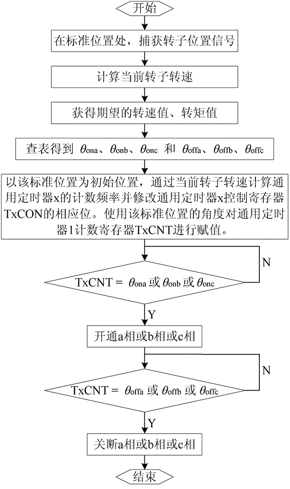
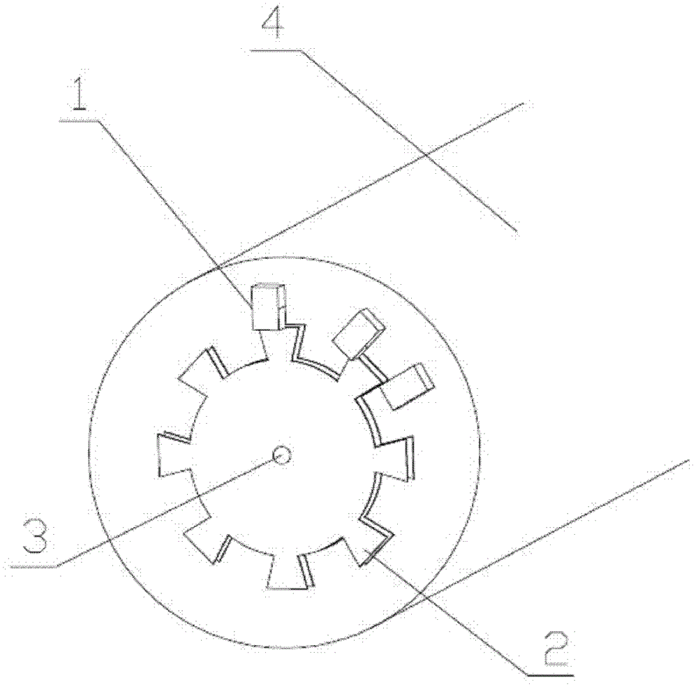
[0013] Taking the three-phase stator twelve-slot and rotor eight-pole switched reluctance motor speed control system based on the TMS320F2812 produced by TI as the control chip as an example, the position detection part of the system is as follows: figure 2 Shown are: three photoelectric tubes 1 at a distance of 15° from each other on the concentric circle of the rotor; a tachymeter disk 2 with eight tooth slots and equal width, which is concentric with the rotor and fixed on the rotating shaft. When the teeth of the tachometer disc 2 block the optical path of a certain photoelectric pair tube 1, the photoelectric pair tube 1 outputs a high level, otherwise it outputs a low level. Because when the output signal of photoelectric pair tube 1 jumps, the rotor position is uniquely determined, so it is defined within one electrical cycle (360° / 8=45°) that the output signal of any one photoelectric pair tube 1 jumps. position is the standard position.

[0014] Such as figure 1 As...


PUM


Abstract

The invention relates to a rotor angle subdivision method for a switched reluctance motor speed regulation system. The method comprises the following steps, which are realized based on software, of: a, calculating a current rotor rotating speed according to a position signal of a rotor of a switched reluctance motor; b, looking up a table to acquire a switch-on angle and a switch-off angle of each phase according to a desired rotating speed and a torque value of the system; c, calculating a counting frequency of a universal timer according to the current rotor rotating speed, modifying a corresponding bit of a control register of the universal timer, and assigning a counting register of the universal timer; and d, when the counting register of the universal timer counts to a certain switch-on angle or a certain switch-off angle, switching on or switching off the phase. The rotor angle subdivision method for the switched reluctance motor speed regulation system is realized based on thesoftware. Compared with the conventional method, the method has the advantages that: the interference capacity is high, the reliability is high, and high-frequency input signals can be detected accurately; furthermore, the subdivision precision of a rotor angle is extremely high; and a driving control circuit is simple and the cost is low.

Description

technical field [0001] The invention relates to a rotor angle subdivision method of a switched reluctance motor speed control system. Background technique [0002] As the price of rare earth permanent magnet material NdFeB (NdFeB) continues to rise, the switched reluctance motor speed control system without permanent magnets is unique because of its simple structure, high efficiency, easy control, efficient stepless speed regulation, and low cost. Advantages It has become a strong competitor of other types of motor speed control systems in the industrial field, and has broad application prospects. However, the current switched reluctance motor speed control system still has the following defects: the stator of the switched reluctance motor, the double salient pole structure of the rotor, and the switching power supply make the switched reluctance motor drive system a multi-variable highly coupled, Systems with severe nonlinearities. The switched reluctance motor speed cont...

Claims


Application Information

Patent Timeline
Patent Type & Authority Patents(China)
IPC IPC(8): H02P6/16H02P25/08
Inventor 花为吴中泽俞贤萍
Owner 江苏华阳智能装备股份有限公司
Why Eureka
Try Eureka