
Apparatus for cracking papermaking waste residues

A cracking device and papermaking waste residue technology, which is applied in the petroleum industry and the preparation of liquid hydrocarbon mixtures, etc., can solve the problems of lack of ash discharge system, continuous and stable operation of production, etc., and achieve the advantages of easy manufacturing, shortening heating time, and ensuring stability Effect

Active Publication Date: 2012-03-07
仁精科技(昆山)有限公司
View PDF6 Cites 5 Cited by
  • Summary
  • Abstract
  • Description
  • Claims
  • Application Information

AI Technical Summary

Problems solved by technology

The multi-row heat pipes of the above equipment can not only strengthen the kettle body, but also improve the heating efficiency of the kettle body to a certain extent, which has certain advantages compared with other existing equipment, but this equipment lacks perfect ash discharge system
Due to the difference between the composition of papermaking waste residue and pure waste plastic and waste rubber, a large amount of ash is generated during the pyrolysis process. The above equipment has serious problems in discharging the ash from the kettle body, resulting in continuous and stable production.

Method used


Image

  • Apparatus for cracking papermaking waste residues
  • Apparatus for cracking papermaking waste residues
  • Apparatus for cracking papermaking waste residues

Examples


Embodiment Construction

[0024] The present invention will be further described below in conjunction with the accompanying drawings.

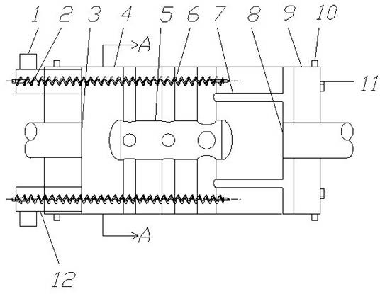
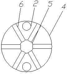
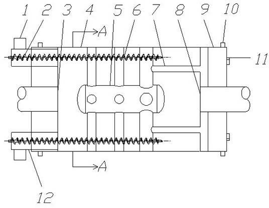
[0025] As shown in the figure, a papermaking waste slag pyrolysis device includes an outer cylinder 4, which is a cylindrical structure, and the center of both ends of the outer cylinder 4 is respectively provided with a feed inlet 8 and a pyrolysis gas outlet 3. The feed port 8 is connected with the feed device, and the cracked gas outlet 3 is connected with the cooling device. In order to enhance the heat insulation performance of the outer cylinder body 4 , a heat insulation layer 9 is fixedly arranged on both end surfaces of the outer cylinder body 4 , and heat insulation sand is filled in the heat insulation layer 9 . On the outside of the heat insulation layer 9, a support wheel 10 for supporting the entire outer cylinder 4 is arranged, and on the heat insulation layer 9 at one end of the feed inlet 8, the transmission gear 11 connected by the external drive devi...


PUM


Abstract

The invention which relates to an apparatus for cracking papermaking waste residues belongs to the technical field of apparatuses for possessing the papermaking waste residues. The apparatus is characterized in that: the apparatus comprises an outer cylinder body and an inner cylinder body which is coaxially arranged in the inner cavity of the outer cylinder body, wherein a cracking gas outlet isarranged at one end of the outer cylinder body and a material inlet is arranged at the other end of the outer cylinder body; several thermal conduction tubes for communicating the inner cavity of theinner cylinder body with the outside of the outer cylinder body are radically arranged between the inner cylinder body and the outer cylinder body; two ends of the outer cylinder body are respectively provided with a thermal insulation layer; the outer wall of each thermal insulation layer is fixedly provided with a support roller with a supporting effect; a transmission gear which has a transmission connection with an outside driving unit is fixedly arranged on the end surface of each thermal insulation layer; a reinforced thermal conduction tube which has an annular structure is axially arranged between the thermal conduction tube close to the material inlet and the end surface of the outer cylinder body; and the reinforced thermal conduction tube is communicated with the thermal conduction tube close to the material inlet and the outside of the outer cylinder body. The apparatus of the invention, which has the advantages of high mechanical strength and high heating efficiency, has a perfect ash discharging system, and can continuously, safely and stably operate, is especially suitable for the high temperature cracking of waste plastic-contained papermaking waste residues.

Description

technical field [0001] The invention belongs to the technical field of papermaking waste residue processing devices, and in particular relates to a papermaking waste residue cracking device capable of continuous, safe and stable operation. Background technique [0002] Due to the low cost and the ability to alleviate the contradiction of insufficient supply of papermaking raw materials, waste paper papermaking occupies a pivotal position in the papermaking industry and shows a growing trend. However, at the same time, waste paper and papermaking also produces a large amount of papermaking waste residue. The so-called papermaking waste residue is the waste residue left after the waste paper has been washed. Its main component is waste plastics and contains a small amount of residual pulp. White pollution", therefore, the problem of papermaking waste pollution needs to be solved urgently. Since the main component of papermaking waste residue is waste plastic, it can be recyc...

Claims


Application Information

Patent Timeline
IPC IPC(8): C10G1/00
Inventor 凌国余戚新军
Owner 仁精科技(昆山)有限公司
Learn More